RS-1_instruction manual.pdf - 第670页
Pa r t 2 D et ai l ed Des c r i pt i o n of Ea c h F unc t i o n Chapte r 6 G e neral - Purpose Vision Co mpone nt 6- 39 the low er rig ht c orner, the “ El em ent D ata ” sc reen r ea p pear s. If you hav e anot her el …
Part 2 Detailed Description of Each Function Chapter 6 General-Purpose Vision Component
6-38
3. Operation on the “Element” screen
①
Type
You can specify a ball or land as an element type of ball components.
This version does not support a column.
When you specify a land as an element, you can select a circular land or rectangular land.
For a bump, specify “Ball” as an element type from the “Type” combo box.
For an electrode that is flat entirely, specify “Land.”
- In the example, a ball is used. Select “Ball” from the “Type” combo box.
②
Reference pos. (position)
The reference position of a ball/land element is the center of an element.
- Select “Center of an element” from the “Reference pos.” combo box.
③
Polarity
This item specifies the brightness of the shot image of an element.
- Normally, the light that illuminates a ball/land element brightly is used for ball
components. Select “Bright” from the “Polarity” combo box.
Note: Since a CBGA illuminates the surroundings of a ball, select “Dark.”
④
Offset
Normally, this setting item is not used. Enter “0” to each field of this item.
⑤
Element size
Enter the size of an element.
Since the shape of a rectangular land is still a square, enter the same value to both the
“Width” and “Length” fields.
- In the example, the diameter is assumed to be 0.5 mm.
Enter the following values.
Width: 0.5
Length: 0.5
- Normally, the “Tolerance” setting item is not used.
Do not change this field setting “0”.
⑥
Ball/Land
For a land, you can select a circular land or rectangular land.
Touch the corresponding check box.
- In the example, a ball element is used, so these check boxes do not appear on the
screen.
⑦
Inspection
To u c h the check box of the item to be inspected.
The check items “Diameter” and “Area” are the same as those for a BGA/FBGA. Specify
the corresponding check level in %. The default value for each check level is 50 %.
Specify the check level of the “Ball exist?” check in %. also However, the percentage
indicates the internal evaluated characteristics. Normally use the default value, “30 %.”
For a land element, this item is handled as “invalid” even though you specify this item, and
the machine does not perform the check to see if a ball exists on a component.
- Normally, the setting item “Average diameter” is not used.
- If you perform the “Diameter,” “Area” and “Ball exist?” checks with specifying the default
value respectively, the following values are used for each check:
Inspection √ Area : 50 % (default)
√ Diameter : 50 % (default)
√ Ball exist : 30 % (default)
Average diameter:
You have to click each check box only.
• Here, you have finished entering data on an element. When you click the <OK> button
at the lower right corner, the “Element Group” screen reappears.
You have finished defining the first element group. When you click the <OK> button at
Part 2 Detailed Description of Each Function Chapter 6 General-Purpose Vision Component
6-39
the lower right corner, the “Element Data” screen reappears.
If you have another element group to be defined, click the <Add> button again to enter
data on the element group. In the example, there are four element groups. Define
four element groups.
When you finish defining all element groups, click the <OK> button at the lower left
corner to finish entering the vision data on a general-purpose vision complex array
component.
All of the entered data is shown below.
Element
Group
Name
First element
position
Layout
inspection
(Dimension)
Missing
Elements
Element
Element
Offset
Element size (Shape) Inspection
ELG0001 X: -6.0
Y: -5.0
Z: 0
θ: 0
Tolerance:
All set to “0”.
0% √ 2D
Count of Column: 9
Pitch: 1.5
Count of Row: 6
Pitch: 1.27
Tolerance: 0
Column
Start: 22
Count: 3
Row
Start: 4
Count: 2
Type: Ball
Reference pos.:
Center of element
Polarity: Bright
Offset: all
set to “0”.
Tolerance:
all set to “0”.
Element size
Width: 0.5
Length: 0.5
Tolerance: all
set to “0”.
(Since an element
is a ball, the
selection screen
does not appear
which allows you to
select a circular or
rectangular shape.)
Diameter: 50
Area: 50
Ball exist?: 30
Average
diameter: 0
ELG0002 X: -8.25
Y: 1.5
Z: 0
θ: 0
Tolerance:
All set to “0”.
0% √ 2D
Count of Column: 12
Pitch: 1.5
Count of Row: 2
Pitch: 1.0
Tolerance: 0
Type: Ball
Re
ference pos.:
Center of element
Po
larity: Bright
Offset: all
set to “0”.
Tolerance:
all set to “0”.
Element size
Width: 0.5
Length: 0.5
Tolerance: all
set to “0”.
(Since an element
is a ball, the
selection screen
does not appear
which allows you to
select a circular or
rectangular shape.)
Diameter: 50
Area: 50
Ball exist?: 30
Average
diameter: 0
ELG0003 X: -7.5
Y: 4.0
Z: 0
θ: 0
Tolerance:
All set to “0”.
0% √ 2D
Count of Column: 5
Pitch: 1.5
Count of Row: 4
Pitch: 1.0
Tolerance: 0
Type: Ball
Re
ference pos.:
Center of element
Po
larity: Bright
Offset: all
set to “0”.
Tolerance:
all set to “0”.
Element size
Width: 0.5
Length: 0.5
Tolerance: all
set to “0”.
(Since an element
is a ball, the
selection screen
does not appear
which allows you to
select a circular or
rectangular shape.)
Diameter: 50
Area: 50
Ball exist?: 30
Average
diameter: 0
ELG0004 X: 1.5
Y: 5.5
Z: 0
θ: 0
Tolerance:
All set to “0”.
0% √ 2D
Count of Column: 5
Pitch: 1.5
Count of Row: 3
Pitch: 0.8
Tolerance: 0
Type: Ball
Re
ference pos.:
Center of element
Po
larity: Bright
Offset: all
set to “0”.
Tolerance:
all set to “0”.
Element size
Width: 0.5
Length: 0.5
Tolerance: all
set to “0”.
(Since an element
is a ball, the
selection screen
does not appear
which allows you to
select a circular or
rectangular shape.)
Diameter: 50
Area: 50
Ball exist?: 30
Average
diameter: 0
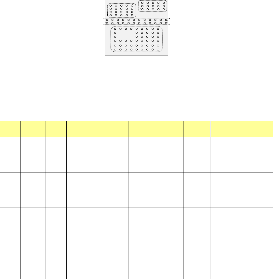
Bottom View
Third element group
(X, Y): (-7.5, 4.0) mm
Pitch of Column: 1.5 mm, Count: 5
Pitch of Row: 1.0 mm, Count: 4
Missing Elements: none
Ball diameter: 0.5 mm
Inspection: Area 50 %
Diameter 50 %
Ball exist? 30 %
Forth element
(X, Y): (1.5, 5.5) mm
Pitch of Column: 1.5 mm, Count: 5
Pitch of Row: 0.8 mm, Count: 3
Missing Elements: none
Ball diameter: 0.5 mm
Inspection: Area 50 %
Diameter 50 %
Ball exist? 30 %
Second element
(X, Y): (-8.25, 1.5) mm
Pitch of Column: 1.5 mm, Count: 12
Pitch of Row: 1.0 mm, Count: 2
Missing Elements: none
Ball diameter: 0.5 mm
Inspection: Area 50 %
Diameter 50 %
Ball exist? 30 %
First element
(X, Y): (-6.0, -5.0) mm
Pitch of Column: 1.5 mm, Count: 9
Pitch of Row: 1.27 mm, Count: 6
Missing Elements:
Start 2 Count 3
Start 4 Count 2
Ball diameter: 0.5 mm
Inspection: Area 50 %
Diameter 50 %
Ball exist? 30 %
Part 2 Detailed Description of Each Function Chapter 6 General-Purpose Vision Component
6-40
Outline recognition component group (Element group/Element format) 6.5.3
♦ An example for entering data on an outline recognition component is shown below.
1. "Element Data" screen
• Select “Outline component” in the “Component Type” field.
• Select check box “Element group/Element format” in the “Define data format” column.
• Click the <Add> button on the “Element Group List.”
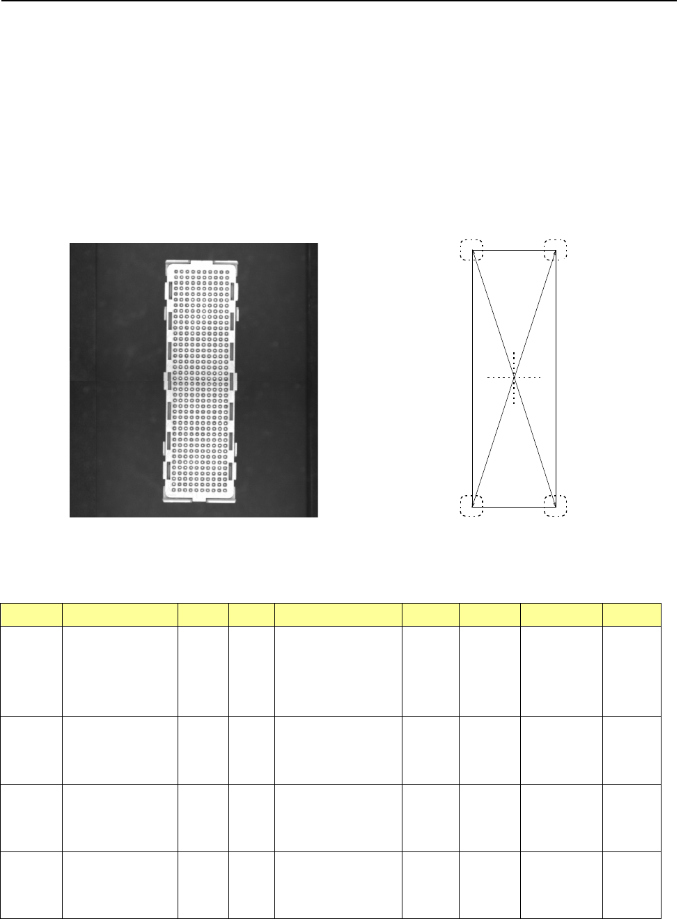
2. Component example 1
• Component appearance and element group positions
<Image of a component displayed on the
component monitor: Bottom view>
<Top view>
Summary of the input data
Element
Group Name
First element position (Layout)
Missing
Elements
Element
Element
Offset
Element
dimensions
(Corner) Remarks
ELG0001 X: -8.25
Y: -27.6
Z: 0
θ: 0
Tolerance:
all values are set to “0.”
Point Type: Corner
Reference pos.: Bottom left
Polarity: Bright
Offset: all
values are
set to “0.”
Tolerance:
all values are
set to “0.”
Radius: 0.5 Light data:
standard
settings of the
reflectance
light
Vertical
two-Split
recognition
ELG0002
X: 8.25
Y: -27.6
Z: 0
θ: 90
Tolerance:
all values are set to “0.”
Point
Type: Corner
Reference pos.: Bottom left
Polarity: Bright
Offset: all
values are
set to “0.”
Tolerance:
all values are
set to “0.”
Radius: 0.5
ELG0003 X: 8.25
Y: -27.6
Z: 0
θ: 90
Tolerance:
all values are set to “0.”
Point Type: Corner
Reference pos.: Bottom left
Polarity: Bright
Offset: all
values are
set to “0.”
Tolerance:
all values are
set to “0.”
Radius: 0.5
ELG0004
X: -8.25
Y: -27.6
Z: 0
θ: 0
Tolerance:
all values are set to “0.”
Point
Type: Corner
Reference pos.: Bottom left
Polarity: Bright
Offset: all
values are
set to “0.”
Tolerance:
all values are
set to “0.”
Radius: 0.5
第 1 エレメントグループ
第 2 エレメントグループ
第
3
エレメントグループ
第 4 エレメントグループ
Fourth element group
Second element group
First element group
Third element group