RS-1_instruction manual.pdf - 第398页
Part 1 B asic O peration Chapter 4 Cr eating a Produc tion Progra m 4- 63 ④ Com p Shape Y ou can specif y the shap e of a component t o be recogn ized with las er . The main applicab le compon ents are des cribed in the …
Part 1 Basic Operation Chapter 4 Creating a Production Program
4-62
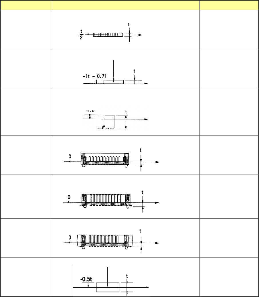
Component type Measurement position Laser height (mm)
Network resistor
Same as that of the
square chip
Trimmer - (t – 0.7)
Unidirectional lead
connector
Bidirectional lead
connector
Z-lead connector
-0.5×t
J-lead socket 0
Gull-wing socket
0
Socket with
bumper
0
Other components
-0.5×t
Note 1: If an angle error occurs when a square chip component such as a 0603 resistor is placed on a
board, change the value specified in the “Laser height” menu item on the “Expansion” tab of the
“Component” data screen to almost “-t/3 (default: -t/2), that is, toward the top side of the
component. It may improve the current condition.
Molding
Component height
Measurement position
with laser
Measurement
position with laser
Component height
Component height
Measurement
position with
laser
-0.5
Measurement
position with laser
Component height
Component height
Measurement
position with
laser
Component height
Measurement
position with laser
Molding
Component height
Measurement
position with
laser
Part 1 Basic Operation Chapter 4 Creating a Production Program
4-63
④ Comp Shape
You can specify the shape of a component to be recognized with laser. The main
applicable components are described in the table below.
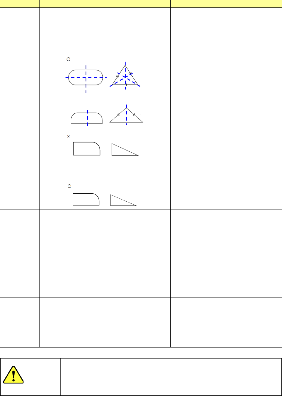
Comp shape
Operation
Applicable components
Config 1
The system detects a tangential line circumscribing
a symmetrical component, calculates a position
error and/or an angle error to correct it (them), and
then places the component on a board.
A symmetrical component means that a line can be
drawn to which the cross section of the measuring
plane of the component is symmetrical with respect.
Standard component type
Config 2
The system detects each side of an asymmetric
component, and calculates/corrects a position error
and/or an angle error to place it on a board.
Irregularly-shaped component specified as
“Others”
Config 3
The system calculates/corrects a positioning error at
the pick-up angle set in the measurement data to
place a component on a board.
Select this setting for a component that has
no vertex such as a cylindrical component.
In this case, the angle is ignored (the polarity
is ignored), and only the center of a
component is obtained.
Config 5
The circumscribed tangent is detected, calculation
and correction of a location difference and an angle
difference are performed and a component with the
line symmetry is placed.
When recognizing component leads ,it's the way
suitable for recognition when light leaks from a gap.
The calculation and the calibration method of a
location difference and an angle difference are
same as the standard component type.
Standard component type
(for lead recognition)
Config 0
The system rotates a component that is ready to be
picked up by the placement angle, and then places
it on a board.
Components that cannot be centered with
laser stably (extremely thin components
whose thickness does not conform to the
specifications):
the system places such a component without
centering it. Therefore, the placement
position is affected by the pick-up position.
CAUTION
The initial setting of the “Comp Shape” is determined according to the
component type. Normally, if you change this initial value, an error may
occur more frequently. Never change the initial value except for the special
component.
Part 1 Basic Operation Chapter 4 Creating a Production Program
4-64
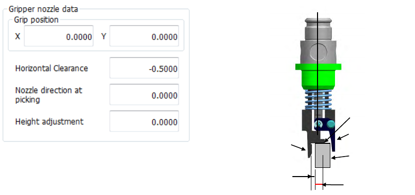
⑤ Gripper nozzle data
Grip position:
Enter a negative value (“-a”) into the “Y” field as the offset from the center of a component to
the side against which a component is pushed (“a”). Do not enter any value other than “0”
into the “X” field.
Horizontal Clearance:
Enter a negative value as the clearance between the side against which the arm on the
gripper nozzle fixed side is pushed and a component (“b”).
Usually, set the default value that is automatically input.
Nozzle direction at picking:
Specify the nozzle direction when the nozzle picks up a component that is supplied at 0
degrees. Specify one of the directions: 0, 90, 180 and 270 degrees.
Height adjustment:
Correction value (clearance between c and the top surface of the component) Normally, set
“- 0.5 mm” to keep a component horizontal.
Grip position (a)
Horizontal
clearance (b)
Component
C
Fixed arm
Swing arm