RS-1_instruction manual.pdf - 第588页
Part 1 B asic O peration Chapter 4 Cr eating a Produc tion Progra m 4- 253 4.5.7 .5 Verify speed This comma nd perf orms pseud o operations: pick - up, recognitio n and placem ent of components to check an err or of each…
Part 1 Basic Operation Chapter 4 Creating a Production Program
4-252
Displayed item
Description
Distance
If the distance between consecutive element groups of a general-purpose vision
component is quite different from the dimension specified in a production program, the
difference is output here.
Side Angle
Angle difference of the detected angle error
6) <Coplanarity screen selection> button
This button displays the coplanarity screen.
7) <Insp.> button
This button runs a coplanarity check.
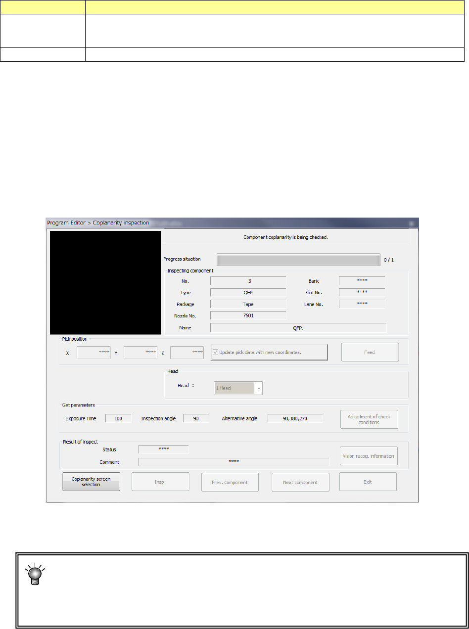
The screen like one shown below is displayed while the machine is running a coplanarity
check.
Data on a component being checked and its pick-up position are displayed on the screen,
and the process being executed is displayed sequentially also.
8) <Exit> button
This button finishes a coplanarity check, and then redisplays the previous screen.
If a terminal number error occurs, measure the component height again or change the
exposure time within a range of 150 to 300.
If a coplanarity error or a colinearity error occurs, check another component or adjust the
threshold value.
Part 1 Basic Operation Chapter 4 Creating a Production Program
4-253
4.5.7.5 Verify speed
This command performs pseudo operations: pick-up, recognition and placement of components
to check an error of each axis, X, Y and θ, and then decides whether the speed specified with a
production program is appropriate or not.
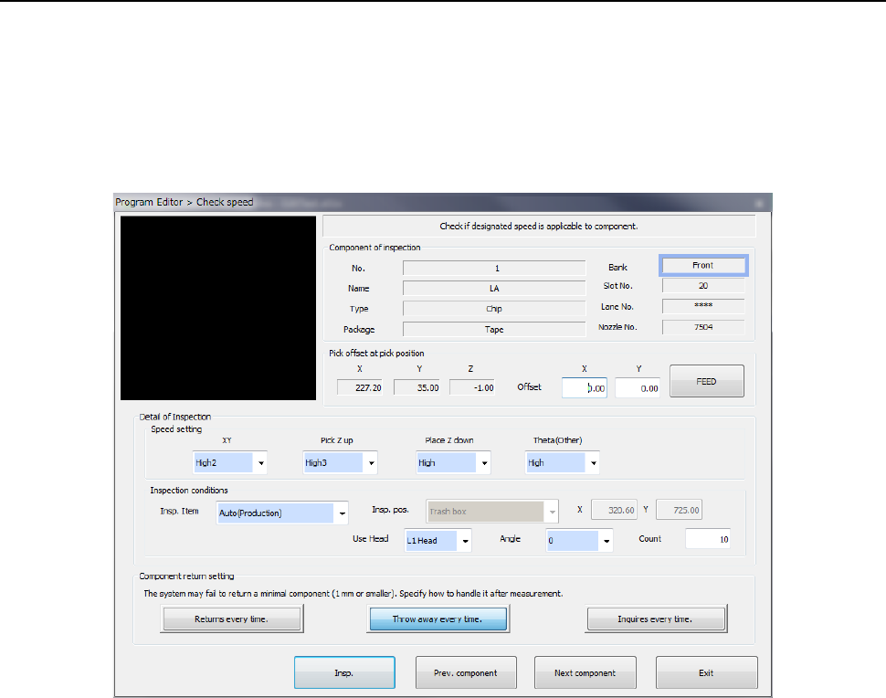
(1) Setting the conditions for checking the speed
When you select the [Meas/Insp] command from the Program Editor menu, and then the [Verify
speed] command, the following “Check speed” conditions setting screen appears.
1) Component of inspection
The data on a component to be inspected appears here.
2) Pick offset at pick position
The data on a component pick-up position appears here. You can change the pick-up
position to that of the previous alternative component or the next alternative component also.
If there is no Pick data created, each menu item is not displayed. So, you cannot change
the component pick-up position, feed the component, or perform the teaching operation.
• Offset
Set this item if you want to shift the component pick-up coordinates.
You can use the teaching function to perform a teaching operation also. You can enter
the pick-up coordinates to change them manually also. However, this setting is not
reflected in the Pick data.
• FEED
Every time you press this button, the system knocks the feeder once to feed the
component (not available with a 32-mm paper tape).
Part 1 Basic Operation Chapter 4 Creating a Production Program
4-254
3) Detail of Inspection
Select what to be inspected. Some inspection items are not selectable
a) Speed setting
Specify the speed to be used for speed check. (The items the system can check vary
depending on your selection in the “Insp. Item” field.)
Selection in the
“Insp. Item” field
Description Remark
XY Inspects the speed at which the XY-axes move.
Pick Z up Inspects the speed at which the Z-axis moves up to
pick up a component.
Available only if the Pick
data is completely created.
Place Z down Inspects the speed at which the Z-axis moves down
to place a component.
Theta(Other) Inspects the speed at which the theta axis rotates.
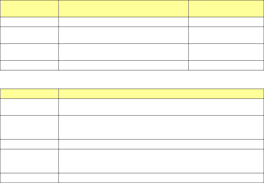
b) Inspection conditions
Menu item Overview
Insp. Item
(Inspection Item)
Select an operation to be inspected: Auto (production), XY, Pick Z up, Place Z
Down, and Theta(Other).
Insp. Pos.
(Inspection position)
Specify either the trash box or the desired coordinates. (You can set the desired
coordinates only when “XY” is selected in the “Insp. Item” list box. The desired
coordinates can be taught also.)
Use Head Specify the head to be used for inspection.
Angle
Specify the placement angle: 0, 90, 180 or 270º. (You can specify this item only
if you select an inspection operation including a component placement in the “Insp.
Item” list box.)
Count Specify the number of times the system will inspect (1 to 100).
4) Component return setting
Select how to handle an extremely small component whose dimension is 1 mm or less after
the system measures it.
• Returns every time
The system returns a component to its previous position every time the system finishes
measuring it.
• Throw away every time
The system discards a component every time the system finishes measuring it.
• Inquires every time
The system asks you how to handle a component every time the system finishes
measuring it.