RS-1_instruction manual.pdf - 第738页
Part 2 D etaile d Descript ion of E ach Functi on Chapter 8 Machine Set up 8- 30 8.3.4 Position setting Component reject position When you se lect [Co mponent reje ct position], the follow ing screen ap pears. (1) S etti…
Part 2 Detailed Description of Each Function Chapter 8 Machine Setup
8-29
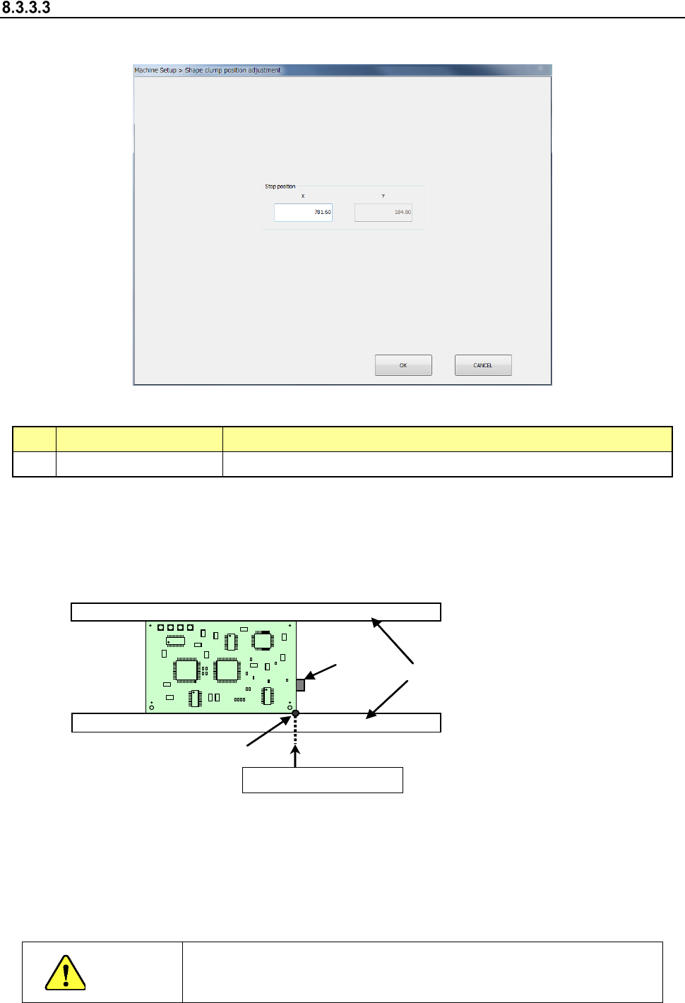
Shape clamp position adjustment
When you select “Shape clamp position adjustment,” the following screen appears.
- “Shape clamp position adjustment” screen
(1) Setting item
No. Item Description
1 X Board clamp stop position with the conveyor stopper
(2) How to set
Perform teaching to enter data on this screen.
Example: When a board is transferred from left to right
To perform teaching, set the conveyor stopper to ON in advance.
Conveyor
Conveyor
stopper
Shape reference position
X (stop position)
* Adjust the rail support (stopper main unit) so that the X-direction position of the tip of the
stopper pin is set as shown below according to the board specifications:
- Standard/XL board specifications
When a board is transferred from left to right: 781.6± 0.5 mm
When a board is transferred from right to left: 131.6 ± 0.5 mm
CAUTION
To avoid a risk of injury, do not put your hand in the machine, nor move
your face or head close to the machine while the machine is teaching
data.
Part 2 Detailed Description of Each Function Chapter 8 Machine Setup
8-30
8.3.4 Position setting
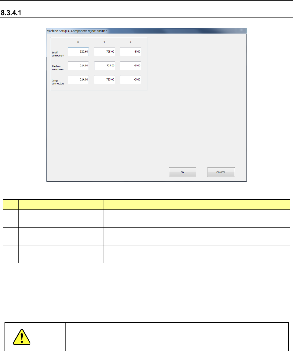
Component reject position
When you select [Component reject position], the following screen appears.
(1) Setting items
No.
Item
Description
1 Small component (X, Y, Z)
Discard position of a small size component
(long side of 15 mm or less)
2 Medium component (X, Y, Z)
Scrapping position
for medium components (components with a long
side of 180 mm or less and a short side of 35.5 or less)
3 Large component (X, Y, Z)
Scrapping position for large components (components with a long
side of 180 mm or less a short side of 50 mm or less)
(2) How to set
1) Enter a value each in the edit box for each of X, Y, and Z.
2) Press the <Teaching> button to enter values. Regardless of which field the input focus
is located in, “X” or “Y,” values are entered in both fields at the same time.
3) To t each the “Z” coordinate, the input focus should be located in the “Z” field.
CAUTION
To avoid a risk of injury, do not place your hand in the machine, nor move your
face or head close to the machine while the machine is teaching data.
Part 2 Detailed Description of Each Function Chapter 8 Machine Setup
8-31
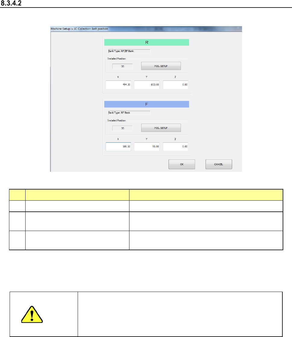
IC collection belt position
When you select [IC collection belt position], the following screen appears.
(1) Setting items
No.
Item
Description
1 Bank type Bank at which IC collection belt is attached
2
IC Collection Belt Installed Position
(Front/Rear, feeder hole number)
Position at which the IC collection belt is attached
3
IC Collection Belt component
discarding position (X, Y, Z)
Position of the IC collection belt at which a component
is discarded
Set each item by teaching or software keyboard.
When the input focus is located in the “X” or “Y” field, values for the X and Y coordinates are
taught. When the input focus is located in the “Z,” a value for the Z coordinate is taught
CAUTION
- To prevent an accident causing an injury, never put your hand in the
machine or bring your face or head close to the machine while it is
teaching data.
- If you optimize a production program without setting the IC collection
belt position, a feeder may be overlapped with the IC collection belt.