RS-1_instruction manual.pdf - 第28页
Part 1 B asic O peration Chapter 1 Overv iew of the Machine 1- 10 Configur ation of the machine Configuration of the board tra nsfer section ・ C onfigur ation of the board t ransfer section (for a sin gl e - lane convey …
Part 1 Basic Operation Chapter 1 Overview of the Machine
1-9
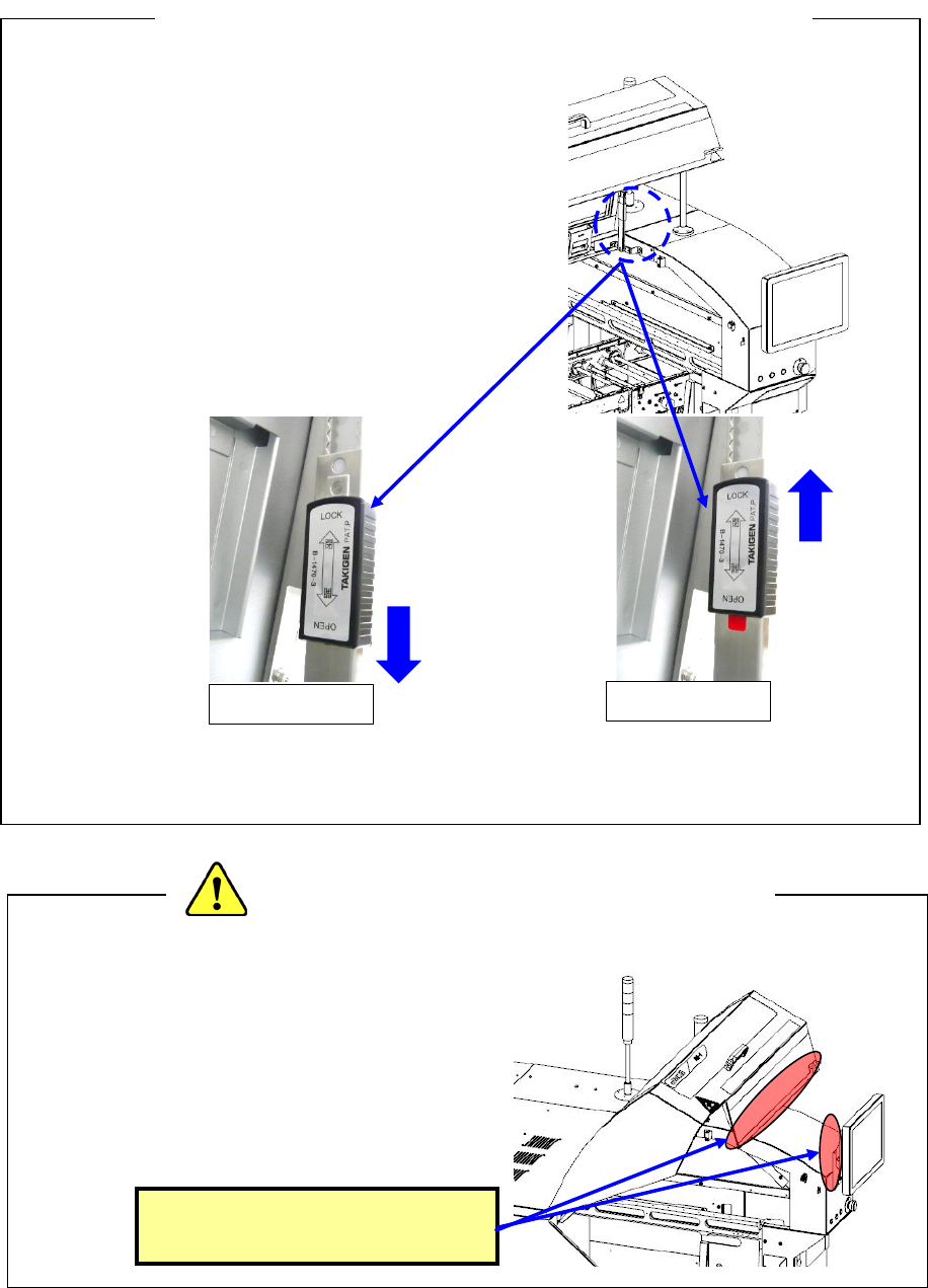
♦ To open the cover, push up the cover and push
the lock lever in the direction of the arrow
(LOCK) for locking.
Release it after confirming the locked status.
* If the cover is released in a non-locked status,
it may fall.
♦ When closing the cover, release the locked status
and then close the cover. Raise the cover and pull
the lock lever in the OPEN direction to release the
lock status.
(During a release operation, take care not to get hurt due to falling of the cover.)
* Do not apply an excessive load to the cover, handle, etc.
♦ When you service the ATC, the XY-axes or
the head, or when you enter the machine to
operate its inside, be extremely careful not to
bump into the cover or the monitor from the
rear side or hit your head on any part to avoid
injury.
<Precaution for operation inside the machine>
<Precautions for opening/closing the safety cover>
Be careful not to hit your head
or other part on these parts.
OPEN
LOCK
Part 1 Basic Operation Chapter 1 Overview of the Machine
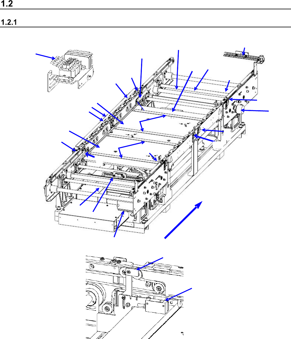
1-10
Configuration of the machine
Configuration of the board transfer section
・ Configuration of the board transfer section (for a single-lane conveyor)
2
1
15
11
3
4
8
10
11
12
10
13
14
17
16
18
11
7
5
9
12
6
21
20
22
23
Board transfer direction
1 IN sensor
9 Board transport electromagnetic
valve
17 Support pin detection sensor light receiving
section
2 OUTsensor
10 Conveyor motor
18 Stopper sensor
3 WAIT sensor fiber light receiving section
11 Drive shaft
19 Stopper
4 WAIT sensor fiber light emitting section
12 Side beam
20 (WAIT2 sensor fiber light receiving section)
5 C-OUT sensor fiber light receiving section
13 Support table IN
21 (WAIT2 sensor fiber light emitting section)
6 C-OUT sensor fiber light emitting section
14 Support table OUT
22 (WAIT2 sensor fiber light receiving section)
7 PWB guide
15 Automatic width adjustment motor
23 (WAIT2 sensor fiber light emitting section)
8 Support table origin sensor
16 Support pin detection sensor light
emitting section
18
19
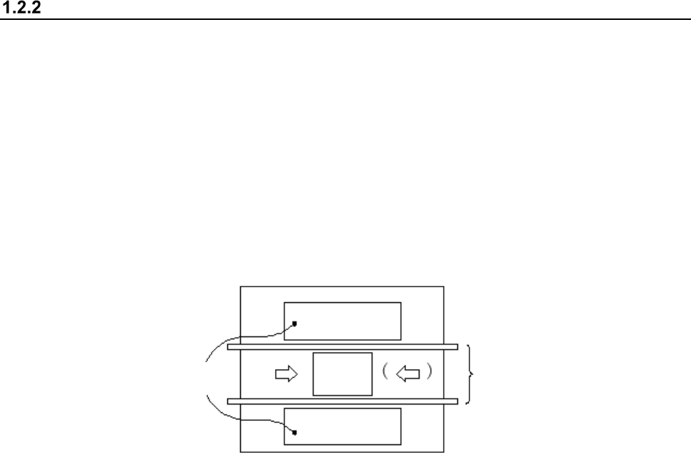
Part 1 Basic Operation Chapter 1 Overview of the Machine
1-11
Configuration of the component feeder
Totally two component feeder banks are provided: one bank is located at the front and rear of the
PWB transport unit respectively. The component supply method varies depending on the package
style of components: tape, or tray.
Components fed by a tape (chip components) or those fed in a stick are mounted on the feeder
bank with using a tape feeder, then carried in the main unit.
A tray component is supplied by a tray holder, a matrix tray changer or a matrix tray server.
A tray holder or matrix tray server, can be mounted on the rear of the machine.
Using the Feeder exchange trolley (option), you can attach and detach the feeder bank from the
mounter and make an external setup.
Feeder banks
PWB
Rear
Front
PWB transport unit
* Left to right transport (IN and OUT are inverted for right to left transport)