RS-1_instruction manual.pdf - 第741页
Part 2 D etaile d Descript ion of E ach Functi on Chapter 8 Machine Set up 8- 33 MTS position offset After you se lect [MT S position of fset], the foll owing s creen appear s. Perfor m an MTS posit ion of fset sett ing.…
Part 2 Detailed Description of Each Function Chapter 8 Machine Setup
8-32
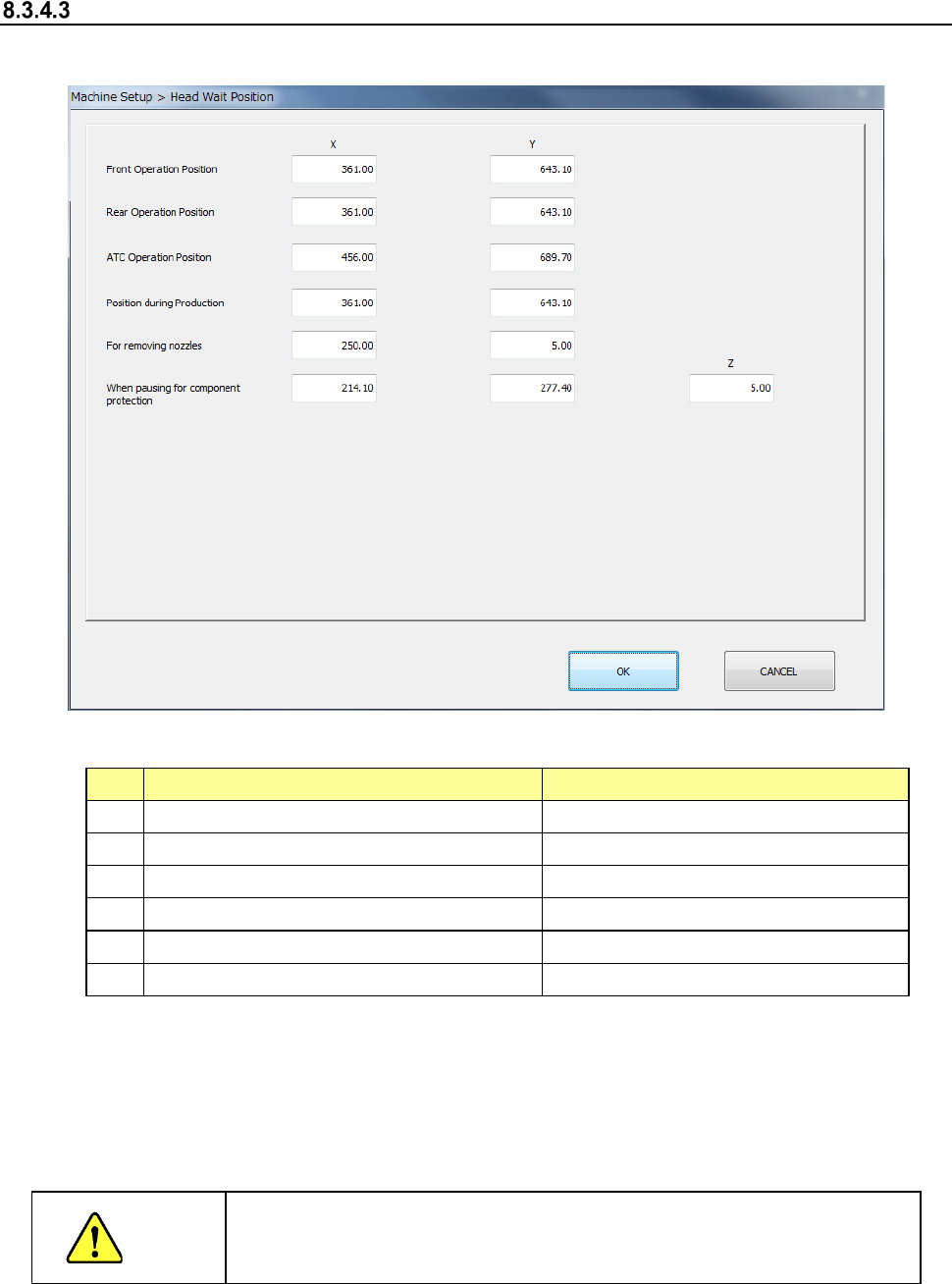
Head Wait Position
After you select [Head wait position], the following screen appears.
1) Setting items
No.
Item
Description
1
Position for front-side operation
X and Y positions
2 Position for rear-side operation X and Y positions
3
ATC Operation Position
X and Y positions
4 Position for production X and Y positions
5
When removing nozzles
X, Y positioning
6
When pausing to protect components
X, Y and Z positions
2) How to set
1) Enter each value in the text box for each of X, Y and Z.
2) Enter each data by teaching. In this case, regardless of which field the input focus is
located in, “X” or “Y,” coordinates are entered in both fields at the same time.
3) To teach the Z coordinate, the input focus should be located in the “Z” field.
CAUTION
To avoid a risk of injury, do not place your hand in the machine, nor
move your face or head close to the machine during while the machine
is teaching data.
Part 2 Detailed Description of Each Function Chapter 8 Machine Setup
8-33
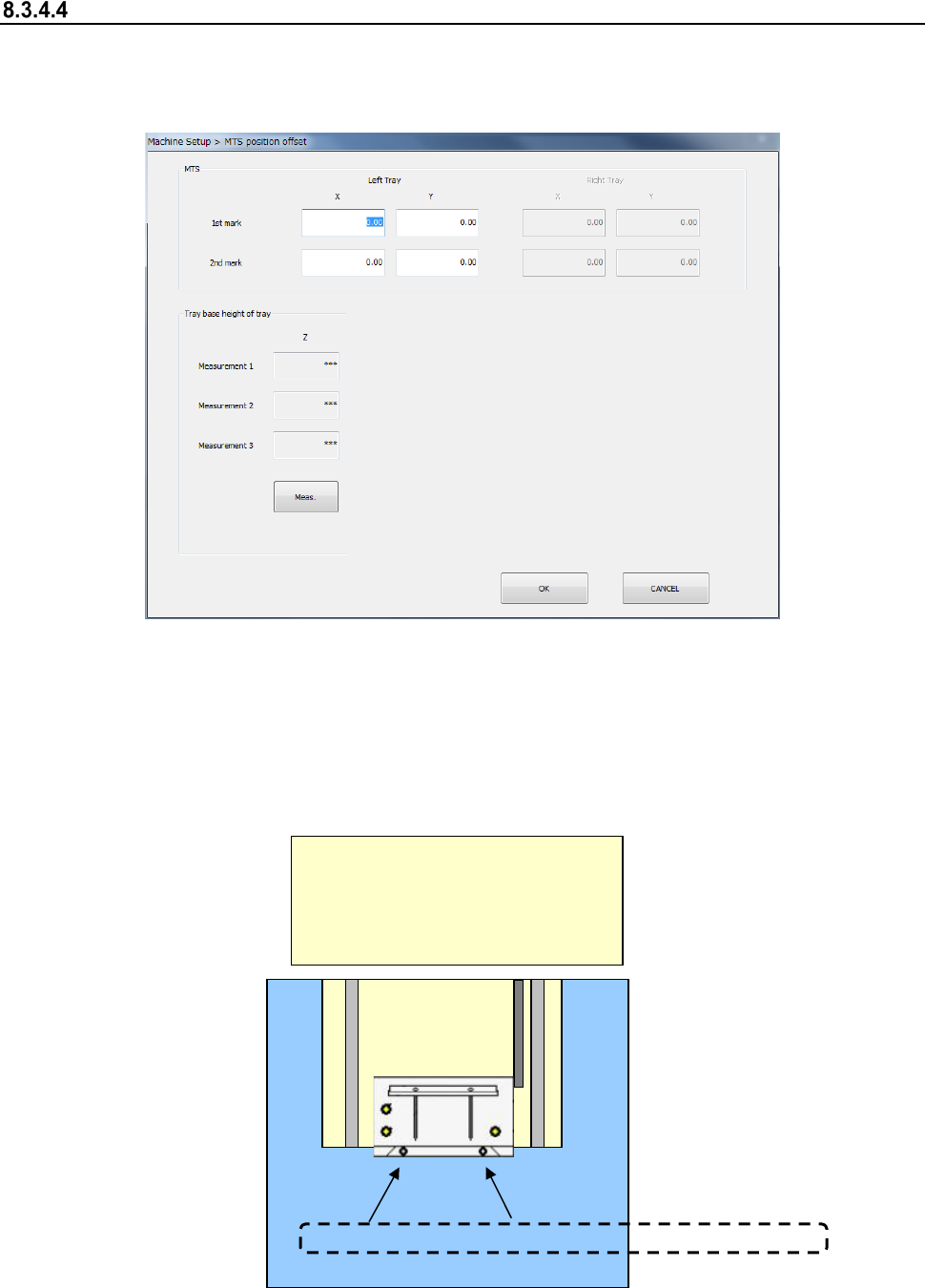
MTS position offset
After you select [MTS position offset], the following screen appears.
Perform an MTS position offset setting.
Set mark position 1/2 of the tray.
(1) Setting item
1) Mark position correction
The mark position correcting function obtains an offset in the horizontal direction
(X, Y) to the design origin of the MTS band mark and corrects the pick coordinates of
the production program at component pick operation.
TR5S/TR5D/TR8SR
<Top surface drawing>
MTS
Front<--->Rear
First mark
Second mark
Mark position correction
Part 2 Detailed Description of Each Function Chapter 8 Machine Setup
8-34
(2) How to set
1) Mark position correction
Perform teaching for the first mark and second mark of the MTS bank marks.
Select a mark item for setting an offset value and press the device key ("HMS" or
"CAMERA") of the teaching panel. Then, the MTS bank marks are drawn out and
teaching is started. Check and adjust the position so that the teaching position may be
the center of the bank mark.
After completion of teaching, the X/Y offset value to the bank mark position on the
design is automatically input.
2 Tray base height display
Pressing the <Meas.> button will display the height at each measurement point.
Refer to the “Installation Guide” of each MTS for the detailed adjustment method.