RS-1_instruction manual.pdf - 第114页
Part 1 B asic O peration Chapter 2 Pr oduction 2-3 Production flowc hart General f low of PWB prod uction START Select the production requirem ents and start up the system. End of production Specify the production requir…
Part 1 Basic Operation Chapter 2 Production
2-2
2.2 Overview
Use the created production program to check that a PWB is placed correctly and produce PWBs.
After creating a new program, perform a trial PWB production before actually producing PWBs in
order to check the PWB placement/pick-up coordinates and perform the final check of the program.
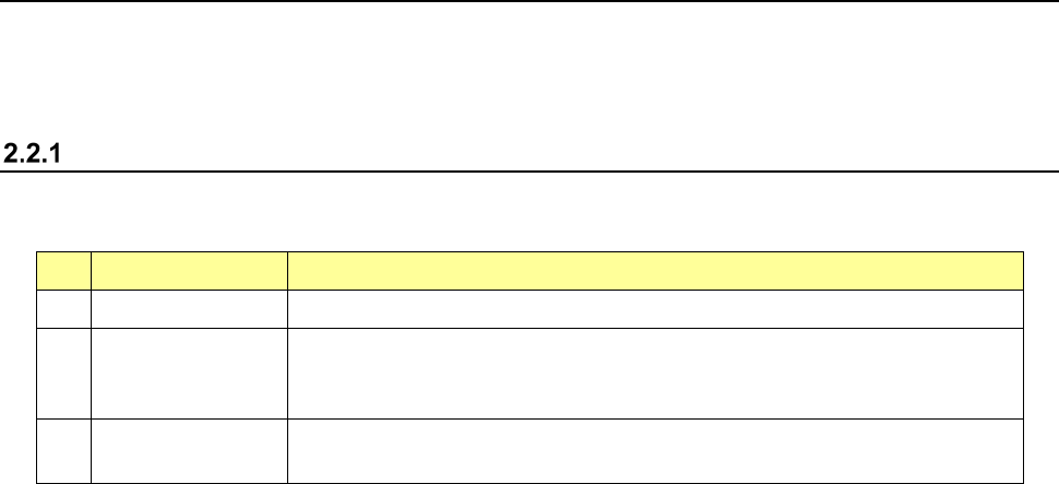
Production mode
The following four production modes are available during production:
No. Production mode Description
1 PWB production Specifies the number of PWBs you plan to produce and produces PWBs actually.
2 Trial Performs a trial PWB production.
You can select the PWB pick-up position tracking function or PWB placement
position tracking function that is to be performed after placement. *1
3 Dry run Checks the PWB pick-up/placement process without using any component.
You can select the PWB pick-up/placement position tracking function. *1
*1 See Section 4.5.6.4 “Component placement position” and Section 4.5.6.5 “Component pick-up
position/component pick-up height.”
The system allows you to specify the requirements for producing PWBs, performing a trial PWB
production, or executing the dry run operation in each mode above.
Part 1 Basic Operation Chapter 2 Production
2-3
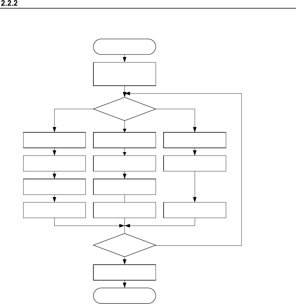
Production flowchart
General flow of PWB production
START
Select the production
requirements and start
up the system.
End of production
Specify the production
requirements?
Specifying of the
production requirements
Set the
number of components.
PWB production Dry run
Specifying of the Dry
run requirements
Specifying of the trial
production requirements
Set the
number of components.
Trial
End?
Specify
the execution mode.
END
Dry runTrial
PWB Production
N
Y
Specify
the execution mode.
Specify
the execution mode.
Part 1 Basic Operation Chapter 2 Production
2-4
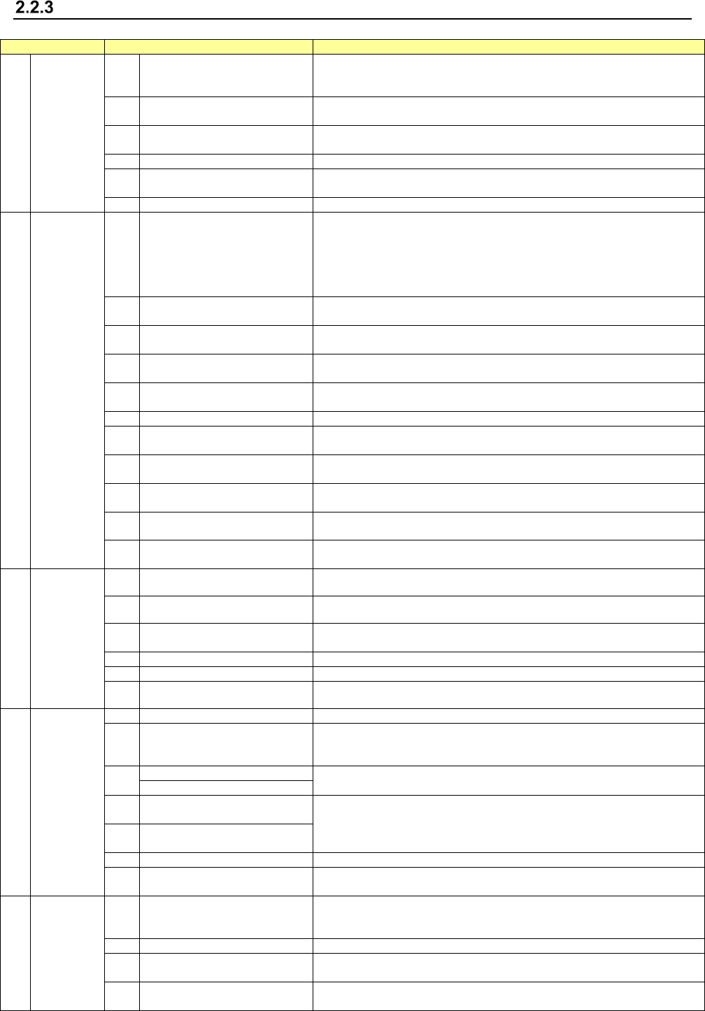
Production main menu configuration
Main menu
Pull-down menu
Description
1 File
1 Open
Loads a production program file.
See “2.6.1 Opening a file (to load a file)” of the section on the program
editing.
2 Save
Saves a program you have edited.
See “2.6.2 Saving a file” of the section on the program editing.
3 Save as
Saves a program with a new name you specified.
See “2.6.3 Saving a file with the desired name.”
4
Get and Save Machine Data
Obtains the machine information and saves it to a file.
5 Save Management Info
Outputs the production management information of a program as a text file
(*.csv).
6
Cont. prod. file Delete
Deletes a continuous production file of the production program.
2 Window
1 Prod Cond.
Displays the production start-up screen: settings you made on the PWB
production requirements /Trial requirements /Dry run requirements
/Operation Option menu.
This menu also allows you to set the conditions to be applied when you
make the common settings, or when you execute PWB production, Trial or
Dry run operation.
2
Production status
(Production condition)
This menu displays the conditions of the facility that is performing PWB
production.
3 Production (Vision)
Displays the recognized mark image and the component image recognized
with a VCS both of which were shot during PWB production.
4 Production status(Action)
This menu displays the data such as the step No. that is being used for
production also.
5 Production status(Zoom)
This menu displays the number of PWBs that are being produced in large
characters.
6
Management Info. (Total)
Displays the accumulated data unique to a production program.
7 Management Info. (Head)
Displays the accumulated data (such as the number of component pick-up
operations that have been performed) per nozzle head.
8 Management Info. (Feeder)
Displays data on each component pick-up position of a feeder (such as the
number of component pick-up operations).
9 Management Info. (Pick ratio)
Displays the PWB pick-up position of each pick-up device or displays the
pick-up rate per level in ascending order (that is, from the worst rate).
10 Electric feeder check Displays the electric feeder condition.
11 Collation Check
You can check the component collation state when you use an IFS-NX
option.
3 Program
1 Retry list (Supplier) Displays the screen showing information on component supply units.
2 Retry list (Not placed) Displays the list of components not placed.
3 Component supply
Displays the “Component supply” screen.
This menu allows you to set the number of components in each Pick data.
4
Edit data
Allows you to change a part of data.
5
Program Check
Checks a production program before start of production.
6 Management Info is cleared Clears the production management information.
4 Support
1
Plan support
Allows you to make preparations before start of production.
2 Placement tracking
Displays the list of component placement positions of a production program
before start of production, and tracks each placement position to check to
see if a component is actually placed on a board.
3
Verify Current check
Allows you to run a verify check.
Verify All check
4
GNRL. Vision direction single
inspection
A general-purpose vision component direction inspection can be made.
5
GNRL. Vision direction
continuous inspection
6
Laser check
Performs a laser height check.
7
Auto-Correct pick position
Clear
Clears information on correction of a component pick-up position.
5 Tool
1 Operation option
Displays the “Operation option” screen.
This menu allows you to make settings of operation to be done during
production.
2
Setting of displayed items
Displays/hides the items of states during PWB production.
3 IFS server reconnection
Reconnects to the IFS server without restarting the machine when you use
an IFS-NX option.
4
Event notification destination
reconnect
When using the external output function, reconnect to the notification
destination without restarting the mounter.