RS-1_instruction manual.pdf - 第149页
Part 1 B asic O peration Chapter 2 Pr oduction 2- 38 ( 3) Dry run No. Item Description 1 Placement range T o limit th e area on which c omponents are plac ed, enter the “ Start step No. ” and “End step No. ” The total of…
Part 1 Basic Operation Chapter 2 Production
2-37
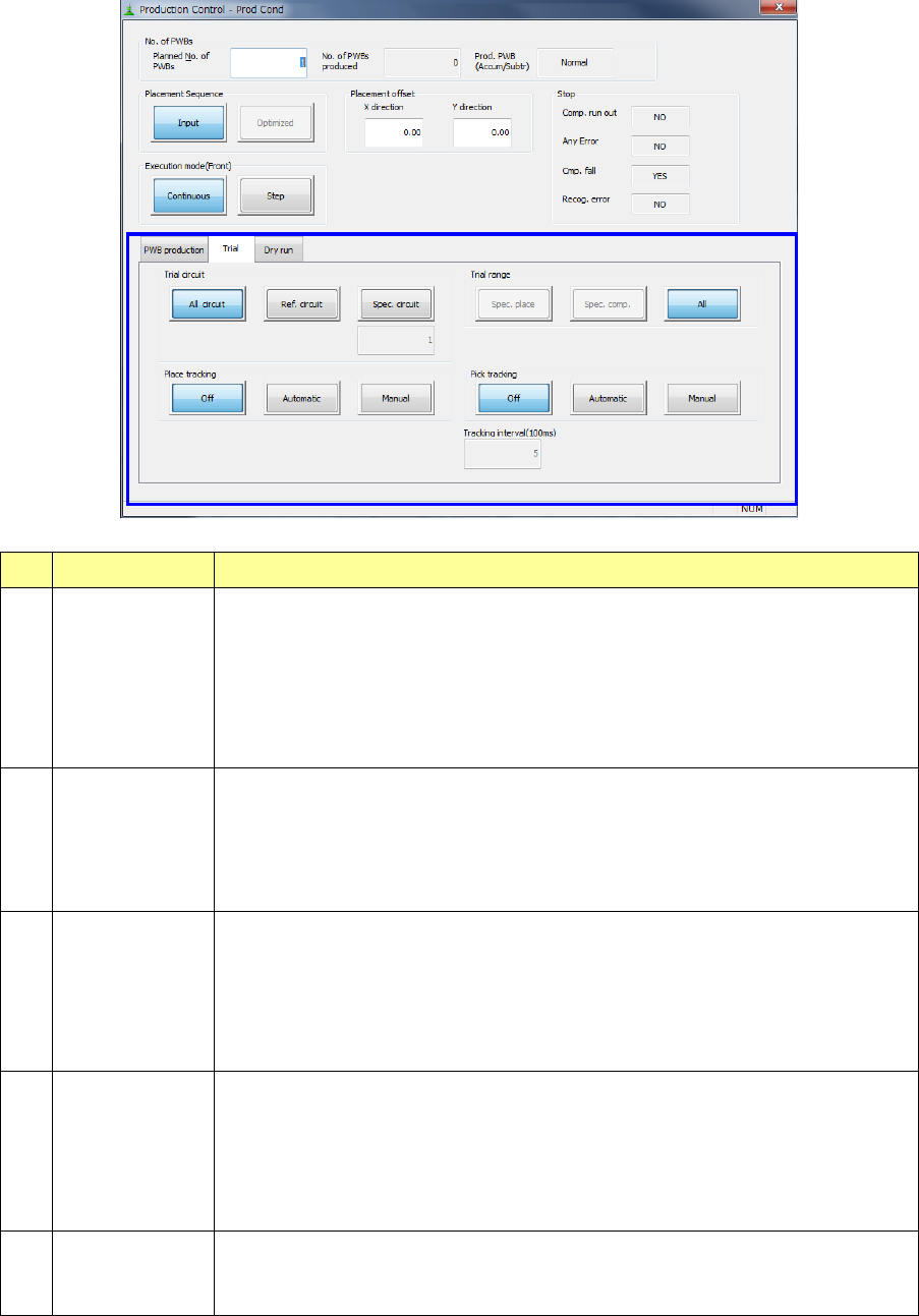
(2) Trial
No. Item Description
1 Trial circuit
Select the desired circuit for trial production. You do not have to make a selection if
you are to produce a single plane PWB.
- All circuit: Components set for trial production are placed on all circuits.
- Ref. circuit: Components set for trial production are placed on reference circuits
only.
- Spec. circuit: Components for trial production are placed on the specified circuits
only
The specified circuit number is shown here.
2 Trial range
Specify the range for trail production.
- Spec place: Components are placed on the placement positions for which “YES”
is selected in the “Trial” field on the Placement data menu.
- Spec comp: All components for which “YES” is selected in the “Trial” filed on the
Component data menu are placed.
- All: Components are placed on all placement positions.
3 Place tracking
After components are placed on a board with trial production, designate whether or
not to perform placement-tracking operation by the camera. If performed, select
whether it is manual or automatic.
- Off: Placement tracking operation is not performed.
- Automatic: Placement tracking is performed automatically.
- Manual: Stops at each placement position, and then goes to the next
placement position in response to input by an operator.
4 Pick tracking
Before components are placed on a board with trial production, designate whether
or not to perform pickup-position tracking operation by the camera. If performed,
select whether it is manual or automatic.
- Off: Pickup-tracking operation is not performed.
- Automatic: Pickup-tracking operation is performed automatically.
- Manual: Stops at each pickup position, and then goes to the next pickup
position in responses to input by an operator.
5 Tracking
When tracking is performed automatically, designate the stop time duration at a
stop position.
The unit is in 100 ms, and 1 is equivalent to 100 ms (0.1 second).
Part 1 Basic Operation Chapter 2 Production
2-38
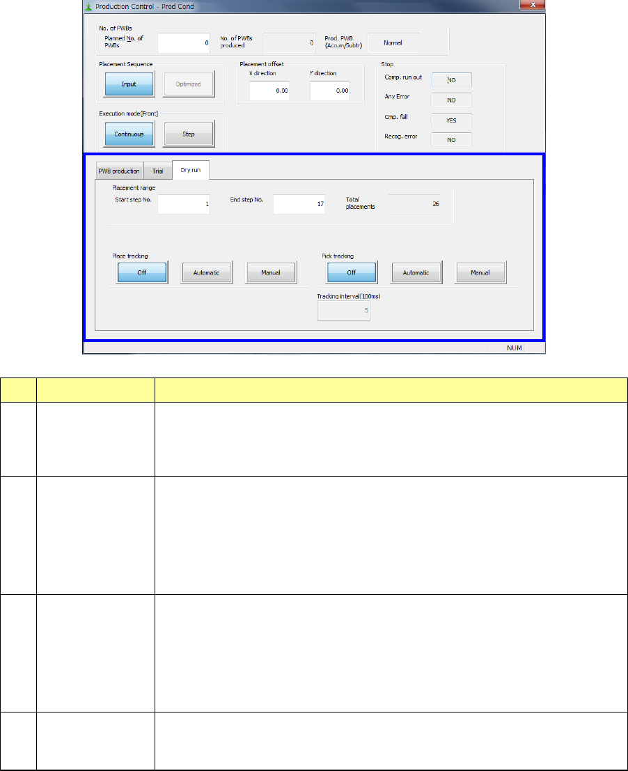
(3) Dry run
No. Item Description
1 Placement range
To limit the area on which components are placed, enter the “Start step No.” and
“End step No.”
The total of step numbers per circuit is displayed in the “Total placements” field.
You can specify this item only when “Input” is selected as “Placement Sequence.”
2 Place tracking
After dry run operation of a board, designate whether or not to perform
placement-tracking operation by the camera. If performed, select whether it is
manual or automatic.
- Off: Placement-tracking operation is not performed.
- Automatic: Placement-tracking operation is performed automatically.
- Manual: Stops at each placement position, and then goes to the next
placement position in response to input by an operator.
3 Pick tracking
Before dry run operation of a board, designate whether or not to perform pickup
position tracking operation by the camera. If performed, select whether it is
manual or automatic.
- Off: Pickup-tracking operation is not performed.
- Automatic: Pickup-tracking operation is performed automatically.
- Manual: Stops at each pickup position, and then goes to the next pickup
position in responses to input by an operator.
4 Tracking
When tracking is performed automatically, designate the stop time duration at a
stop position.
The unit is in 100 ms, and 1 is equivalent to 100 ms (0.1 second).
Part 1 Basic Operation Chapter 2 Production
2-39
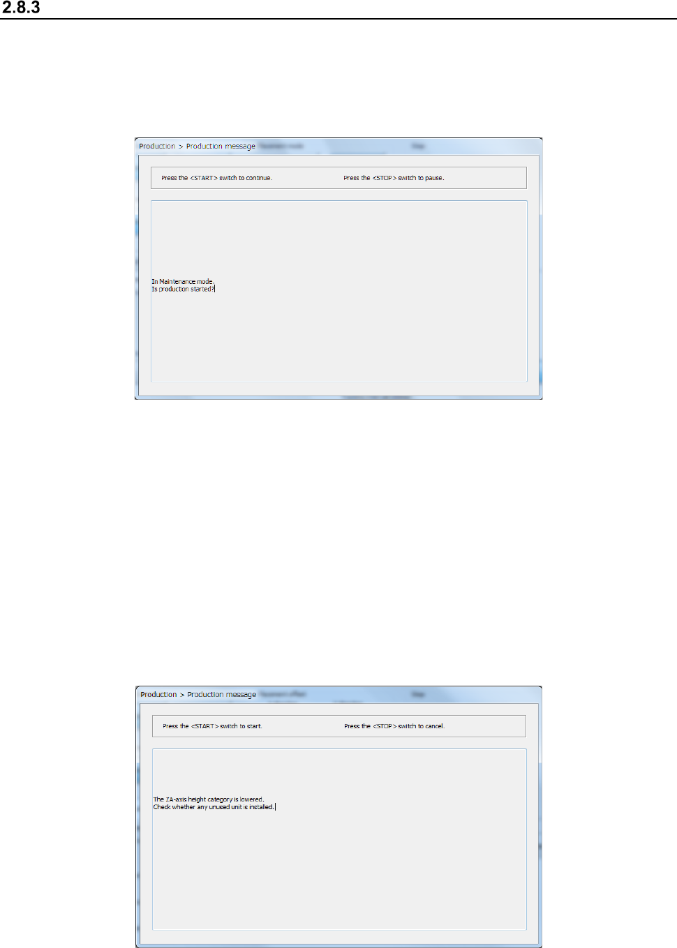
Start of production
Specify the production requirements, and then press the <START> switch on the operation panel.
When the <Maintenance Key> is set to Maintenance mode, the following screen appears. Set the
<Maintenance Key> to Production mode, and then press the <START> switch on the operation
panel. If you do not want to start PWB production, press the < STOP> switch on the operation
panel.
When you press the <START> button to start PWB production, one of the following screens
appears according to the previous setting: “Production status (Production condition)” screen (see
Section 2.8.3.1 “Production condition”), “Production status (Vision)” screen (see Section 2.8.3.2
“Vision”), “Production status (Operation condition)” screen (see Section 2.8.3.3 “Operation
condition”), and “Production status (Number of produced PWBs)” screen (see Section 2.8.3.4
“Number of produced PWBs”).
If the system has never performed the origin return operation before you press the
< START > switch, press the < START > switch at first to return each device to its home position,
and then press the < START > switch again.
When the ZA-axis operates at a 3mm-height at the production start, the following notice message
will appear. Carefully check that there is no unused unit that interferes with the head, and then press
the <START> switch again.