RS-1_instruction manual.pdf - 第907页
Part 2 D etaile d Descript ion of E ach Functi on Chapter 12 Handling th e Optional Device s 12 - 23 (6) Connect each ca bl e and t he ai r tube to t he “Power connector for the MTS,” “Interf ace connector ” and the “ φ6…
Part 2 Detailed Description of Each Function Chapter 12 Handling the Optional Devices
12-22
* To use a TR5SNX or TR5DNX that has been remodeled already and whose software has been
upgraded with an RS-1/1R or another machine model, follow the instructions described in
Sections 12.3.7 and 12.3.8.
To avoid any accident caused by sudden activation of the machine, turn
off the power.
12.3.6.1 How to install
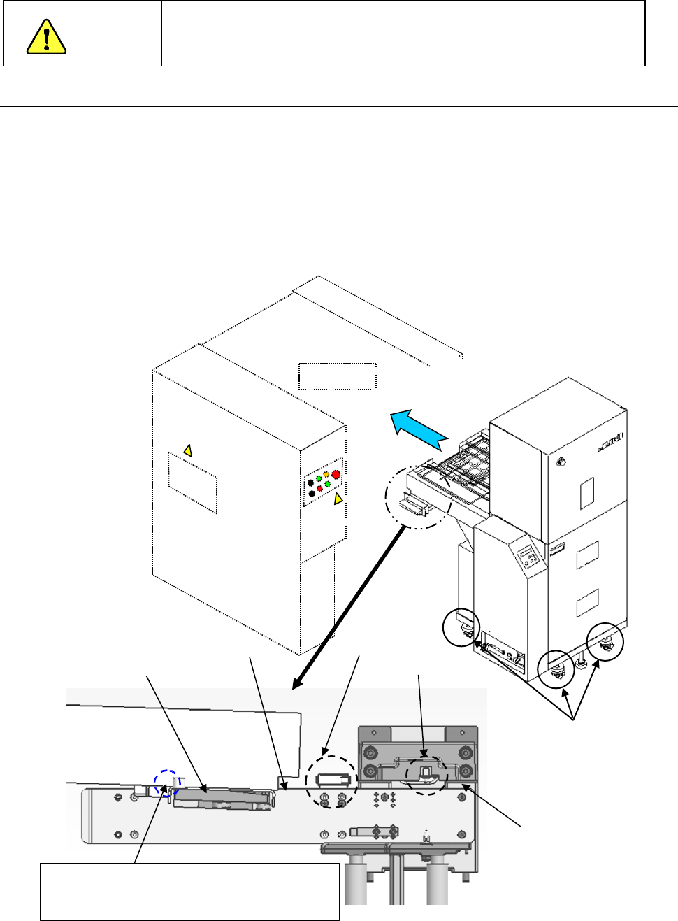
(1) Move down the rear bank of the main unit.
(2) Adjust the caster adjusters 1 of the MTS so that the reference side of the bank support 2 of
the main unit can be aligned with the top side 3 of the joint block of the MTS to level them.
(3) Turn the caster adjusters only on the front side of the MTS so that the topside 3 of the joint
block will be aligned with the upper edge of the guide roller (approximately ± 3 mm).
(4) While the safety cover is closed, install the MTS into the machine main unit gently from the
rear side of the main unit.
(5) Confirm that the MTS has been inserted to the rear of the main unit, and then move up the
bank.
Upper edge of the
roller guide
Mechanical
valve
CAUTION
Mounter
①
③
②
Adjust the caster adjusters so that the height of
this part of the joint block topside can be the same
as that of the top edge of the guide roller
Topside of the
joint block
Bank switch
Part 2 Detailed Description of Each Function Chapter 12 Handling the Optional Devices
12-23
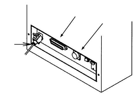
(6) Connect each cable and the air tube to the “Power connector for the MTS,” “Interface
connector” and the “φ6 tube take-up port for the MTS” provided on the interface panel on the
right side of the mounter.
(7) Turn on the power supply of the matrix tray server, and set the menu items "Device enable"
and " MTS position offset” invoked from the “Machine Setup” screen.
①
②
③
TR5SNX/5DNX
①
Power connector for the MTS
② Interface connector for the MTS
③ φ6 tube take-up port for the MTS
Part 2 Detailed Description of Each Function Chapter 12 Handling the Optional Devices
12-24
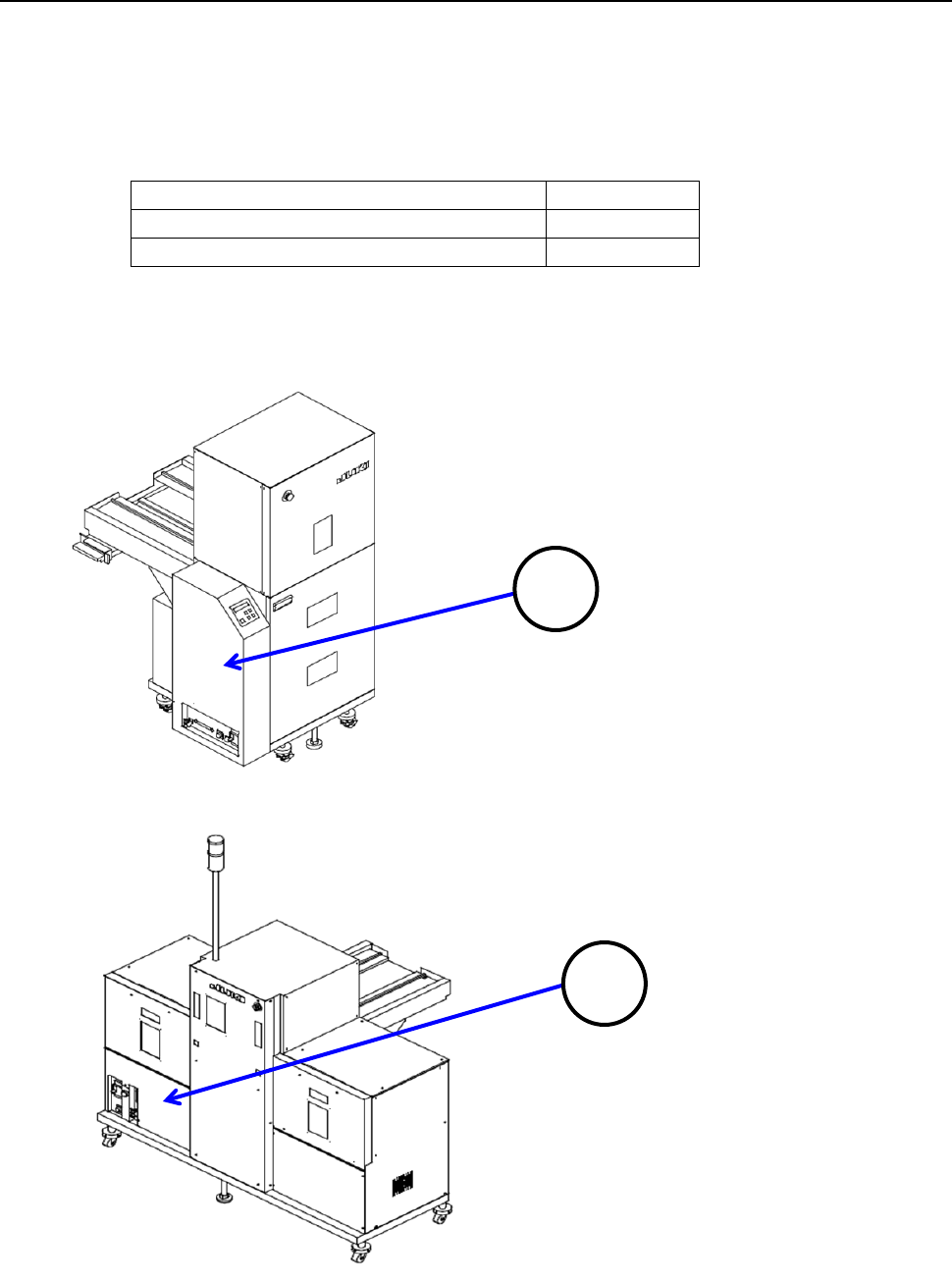
12.3.7 Setting the MAIN board (TR5SNX/TR5DNX)
You have to set the DIP switch of the MAIN board of an MTS other than a TR8SR.
The DIP SW 6-2 is set to OFF at the factory.
If you use with an RS-1/1R a TR5SNX/TR5DNX that was used with another machine model, you
have to change the setting of this DIP SW 6-2 to ON after remodeling the MTS and upgrading the
MTS software.
Machine model an MTS is connected to
DIPSW6-2
RS-1/1R
ON
Other than an RS-1/1R
OFF
To check the MAIN board, remove the cover 1 in case of the TR5SNX or the cover 2 in case of the
TR5DNX.
1
2