RS-1_instruction manual.pdf - 第385页
Part 1 B asic O peration Chapter 4 Cr eating a Produc tion Progra m 4- 50 6) Package size If the size of a por tion on which t he laser beam strikes of a component such as a bos s LED lens comp onent is dif ferent fr om …
Part 1 Basic Operation Chapter 4 Creating a Production Program
4-49
Example:
5) Centering method
Specify the method of obtaining the center of the component.
Select this method according to the component (in consideration of specifications, accuracy,
and tact). However, available centering methods are limited depending on the component
type.
Component type
Laser
Vision
Component type
Laser
Vision
Square chip O O BGA O O
Square chip p (LED) O X FBGA X O
Melf O X Outline-recognized component X O
Elec. Cap. (Aluminum electrolytic capacitor) O O General-purpose vision component X O
GaAsFET O O RNA (Network resistor) O X
SOT O X Trimmer O X
SOP O O One-direction lead connector O O
HSOP O O Two-direction lead connector O O
SOJ O O Z-lead connector O O
QFP O O Expanded-lead connector X O
QFN O O J-lead socket O O
PLCC (QFJ) O O Gull-wing socket O O
PQFP (BQFP) O O Socket with bumper O O
TSOP O O Other O X
TSOP2 O O
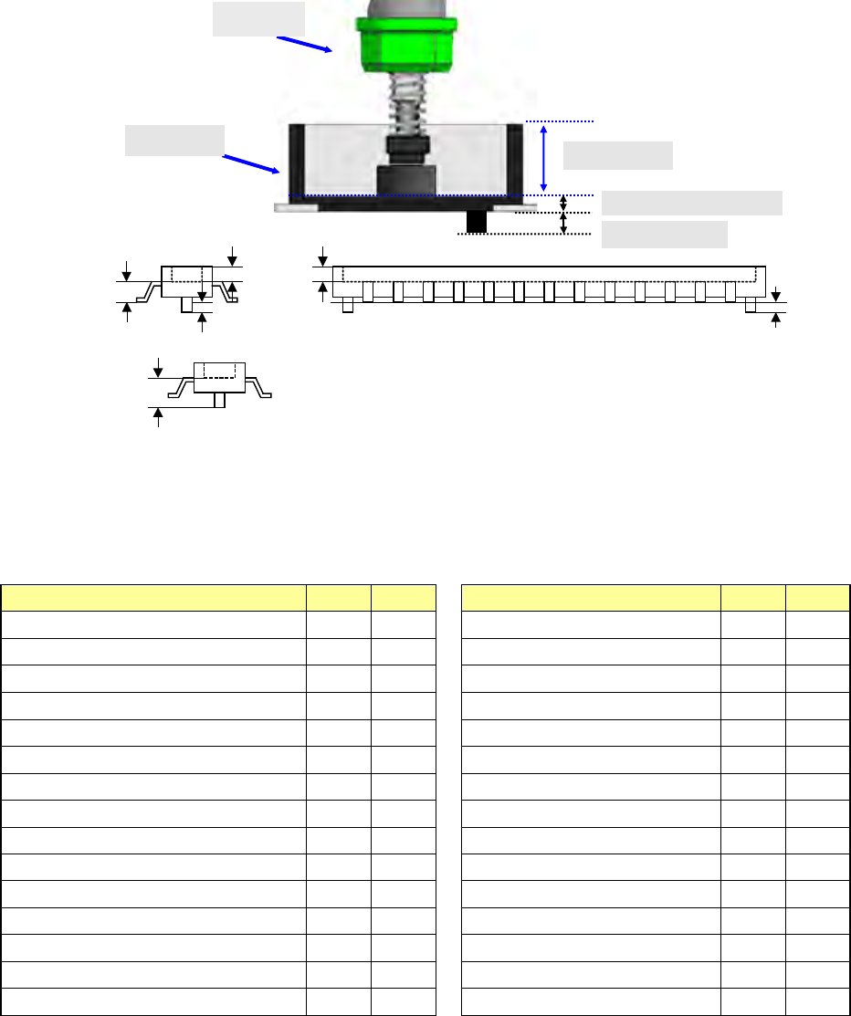
Component
height measured
with laser
Component height
Pick depth
Boss height
Boss height
Component height
Pick depth
Nozzle
Boss height
Connector
Part 1 Basic Operation Chapter 4 Creating a Production Program
4-50
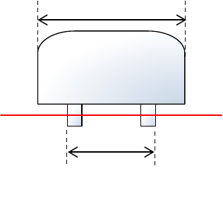
6) Package size
If the size of a portion on which the laser beam strikes of a component such as a boss LED
lens component is different from that of the package part (body) when the component is
recognized, enter the package size (PW/PL) here.
7) <OK> button and <Cancel> button
When you press the <OK> button, the system validates your editing and quits the “Form”
screen.
When you press the <Cancel> button, the system discards your editing and quits the “Form”
screen.
When you quit the “Form” screen, the system redisplays the “Placement” data screen if you
invoke the “Form” screen from the “Placement” screen, or the “Component” data list screen
if you invoke the “Form” screen from the “Component” data list screen.
If you quit the “Form” screen with any method other than buttons (by the menu command or
by selecting a tab), the system executes the same process as when you press the <OK>
button.
Package (PW/PL)
Outline(W/L)
Part 1 Basic Operation Chapter 4 Creating a Production Program
4-51
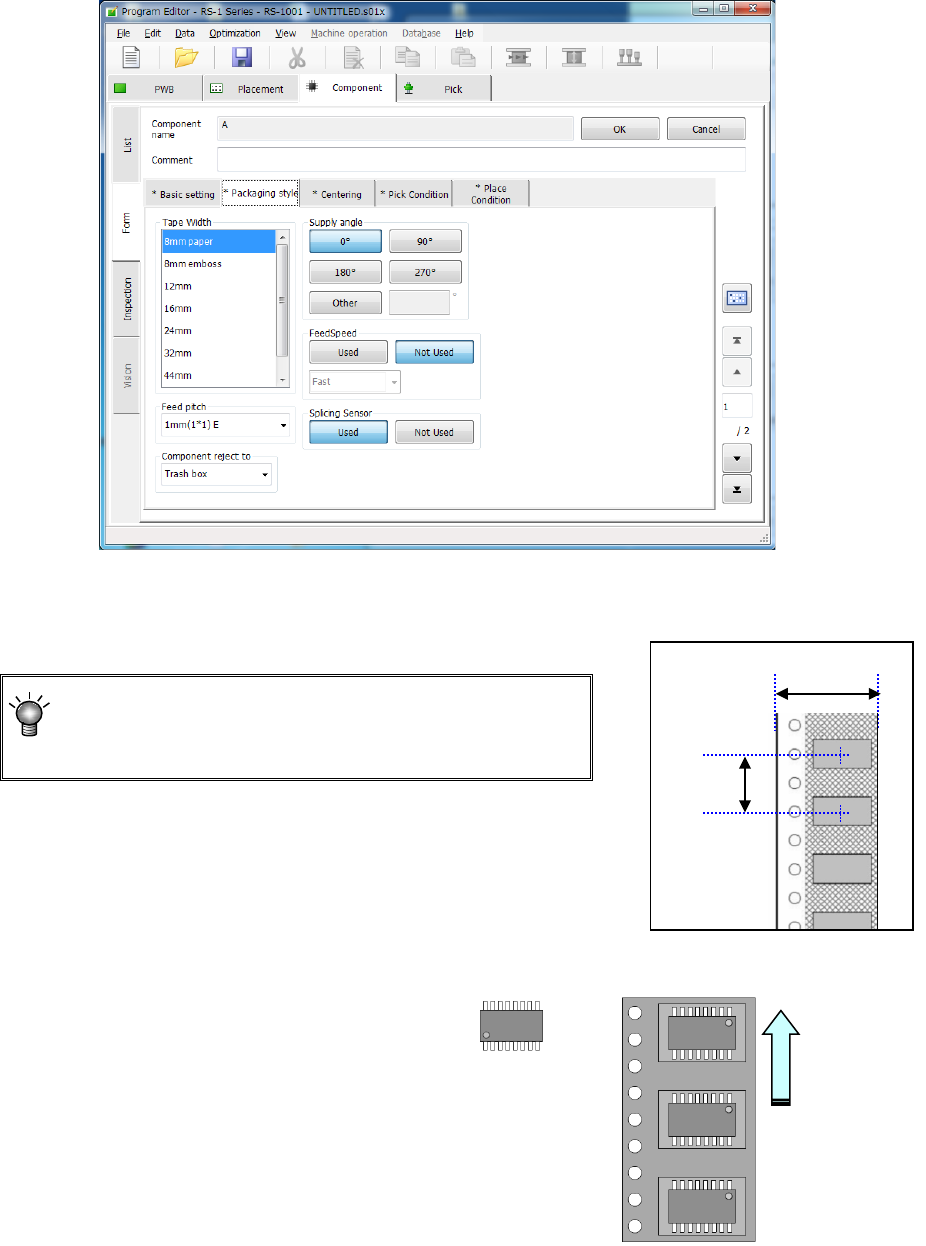
(2) Packaging style
The displayed items vary depending on your selection in the “Packaging style” field of the “Basic
setting” tab sheet.
1) How to enter data when you select “Tap e ” as the “Packaging style”
① Tape width
A list of selectable feed units is displayed in the list box. Select a feed unit in this list.
② Feed pitch
Select the tape feeding pitch.
For tapes with a size of 12 mm to 88 mm, set the pitch
of the component data corresponding to the feed pitch
setting on the tape feeder side.
Example) When 12mm-tape is fed 8 mm,
8 mm (4*2) Pitch = 8 mm (feed amount 4 mm x
twice)
* For the setting of the tape feeder side, refer to the "Instruction
Manual" of the corresponding tape feeder.
③ Component Supply angle
Enter the angle of a component package
on the tape feeder with respect to the
component placement angle, 0 degrees.
When you select “Other,” enter the angle
in the edit field. (0° to 359.9875°)
See the table below for the JUKI’s
definition of the component supply angle.
Tape
Pitch
Angle definition 0°
Supply angle 180°
Feed direction