RS-1_instruction manual.pdf - 第536页
Part 1 B asic O peration Chapter 4 Cr eating a Produc tion Progra m 4- 201 • Patterns regist rable as a u ser - specified tem plate 1) Patterns registr able as a u ser - specified temp late ① Wi ring pat tern ② Pad/land …

Part 1 Basic Operation Chapter 4 Creating a Production Program
4-200
4) Teaching the detection frame
When you finish the operation (3), the system automatically displays the window whose size
is 1.5 times that of the frame you set at (1) so that it can be aligned with the center of the
screen (default window).
To change the detection frame, follow the procedure described at (1).
If you do not change the detection frame, press the <OK> button.
When you press the <Prev> button at this point, the system returns to the procedure for teaching
operation of the scale frame.
5) End of teaching
When the system finishes teaching operation for recognizing the template, it displays (*)
next to the mark on the "Program Editor" screen indicate that it finished teaching operation.
Perform the teaching operation for recognizing a mark for all marks to be used.
If you press the <CANCEL> button during teaching, the system finishes teaching at that
point (in this case, the data that has been entered until that point will become invalid).
Even though you press the <CANCEL> button, any device will not move.
• Notes on setting of a template
i) Check to see if there is no pattern similar with the template you set inside the detection
frame.
ii) Set the size of the pattern to 0.5 mm to 3 mm in the same manner as a standard mark.
iii) Specify the designed values (CAD data) as coordinates. The system cannot obtain the
center position correctly when it teaches the user-designated template. Since the system
teaches the pattern by moving the crosshair cursor, the position you specified is regarded
as the center position as it is (Since the system calculates and sets the center position for
the standard mark pattern, any error is not generated).
iv) You cannot execute the [Vision Copy] command for any user-designated template.
Set the detection frame.
Follow the procedure for setting the scale frame.
A
dotted
line indicates the frame for setting a template, but it
is no
t displayed on the screen actually.
The message “Set Left
-Top Point” is displayed on the
bottom of the screen.
When you finish adjusting the frame, press the <OK> button.
The message “Set Right
-Bottom Point” is displayed on the
bottom of the screen.

Part 1 Basic Operation Chapter 4 Creating a Production Program
4-201
• Patterns registrable as a user-specified template
1) Patterns registrable as a user-specified template
① Wiring pattern
② Pad/land pattern that is not screen-printed (without solder paste)
③ PWB mark other than the JUKI standard (whole or a part)
2) What is required for registration as a user-specified template
The through-hole/pier hole pattern creating process is different from drilling process,
so that the same positional relation cannot be provided at all times. (The hole
position for the pattern is unstable.)
To register the template on the basis of the through-hole/pier hole, register this
template including peripheral wiring pattern instead of registration of itself.
3) What cannot be registered as a user-specified template
① Silk (character) printing pattern
The pattern/pad creating process is quite different from the silk printing process, so
that the placement position cannot be determined on the silk pattern.
② Screen-printed pad/land pattern
The screen-printed solder paste is granular. Accordingly, the luminous status
varies depending on the environment and conditions. Template matching is
resistant to changes of lighting conditions but cannot follow changes of polarity
(normal/reverse rotation).
③ A similar pattern exists on the recognition screen.
④ Template with a small difference between brightness and darkness
⑤ The pattern selection (size) or angle changes.
In particular, when a part of the pattern is registered as a user-specified template, the scale
change is incorporated into the recognition accuracy as it is. Register the whole pattern as
a user-specified template.
Regarding an angle change, its effect is increased (the recognizing position is shifted) as the
position of center of gravity (described before) of the template is separated from the center of
the template.
Set the user-specified template so that the center of gravity may be coincident with the center
of the template if possible.
Part 1 Basic Operation Chapter 4 Creating a Production Program
4-202
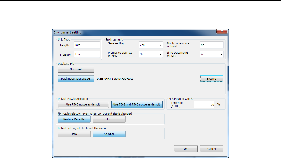
4.5.5 Environment setting
This section describes how to set the environment for editing a production program.
When you select the [File] command on the Program Editor menu, and then the [Environment
Setting] command, the “Environment setting” screen appears.
(1) Unit Type
Set units of length and pressure when you edit a program.
• Length: Select a unit among mm, 1/100 mm and inch.
• Pressure: Select a unit, either kPa or level.
(2) Environment
1) Save setting
Select whether to save the conditions under which you quit the Program Editor and replicate
it when the Program Editor starts up next time.
• Yes: The grid width of each list screen is reproduced at the next program edit launch.
• No: The grid width of each list screen is initialized when you start up the Program Editor
the next time.
2) Prompt to optimize on exit
Select whether to display the message for optimization when you quit the Program Editor.
• Yes: The system displays the inquiry dialog box that asks you whether to execute the
Optimization function if you try to quit the program although you have not executed the
optimization function.
• No: The system does not display the inquiry dialog box.
3) Notify when data entered into DB
Select whether to notify you that the system finishes registering data in the database.
• Yes: The system notifies you that it registered component data into the database when it
did.
• No: The system does not notify you.
4) If no placements remain, delete comp. record
Select whether to delete component data on a component used at the placement position
when the corresponding placement data is deleted.
• Yes : The system deletes component data when all the corresponding components
have been placed at the placement positions.
• No : The system does not delete component data.
You can delete component data that has no placement positions on the