RS-1_instruction manual.pdf - 第237页
Part 1 B asic O peration Chapter 2 Pr oduction 2- 126 (1) P ro gres s si tuat ion This progre ss bar ind icates how far t he check has pr ogressed. When the syst em finish es contin uous inspec tion, it o utputs the foll…
Part 1 Basic Operation Chapter 2 Production
2-125
The system returns a component to its original position.
2) Throw away every time
The system discards a component according to the setting of the menu item “Comp
reject to.”
3) Inquiries every time
The system displays the “Question” screen every time it finishes inspecting one
component.
(4) <Continuous Inspection> button (or the <START> switch)
The system starts checking the laser position of components continuously.
CAUTION
Immediately after you press the <Continuous inspection> button, the head starts moving and the
system starts a check.
To avoid injuries, do not put your hands inside the machine or keep your face or head away from
the machine.
Before pressing the <Continuous inspection> button, check to see if there is no one who is working
the internal parts of the machine.
Before pressing the <Continuous inspection> button, check to see if there is no one who is near
the machine and may be injured.
Before pressing the <Continuous inspection> button, check to see if there is no obstacle such as
an adjustment tool that is located or attached inside the machine and may prevent the machine
from operating normally.
(5) Exit
When you press this button, you can go back to the previous screen.
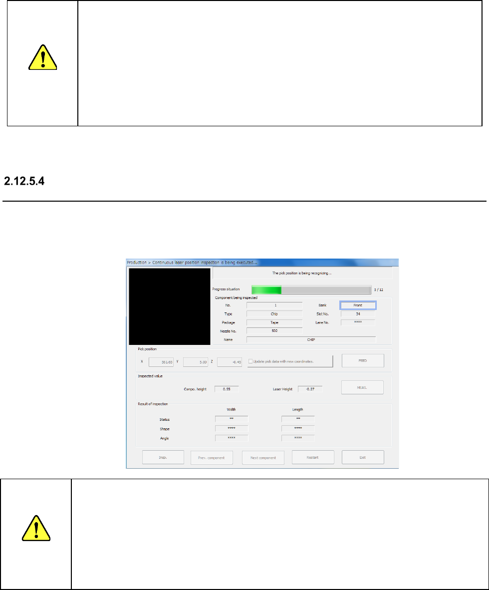
“Continuous laser position inspection being executed” screen (“Laser position
inspection”)
While the system is inspecting the laser position continuously, it displays data on the component
being inspected, its pick-up position and laser position as well as what is being processed.
If the laser check detects an error, you can perform the laser position inspection function or laser
position measurement function on this screen.
CAUTION
Immediately after you press the <Insp.> button, the head starts moving and the system starts
inspection.
To avoid injuries, do not put your hands inside the machine or keep your face or head away from the
machine.
Before pressing the < Insp.> button, check to see if there is no one who is working the internal parts of
the machine.
Before pressing the < Insp.> button, check to see if there is no one who is near the machine and may
be injured.
Before pressing the < Insp.> button, check to see if there is no obstacle such as an adjustment tool
that is located or attached inside the machine and may prevent the machine from operating normally.
Part 1 Basic Operation Chapter 2 Production
2-126
(1) Progress situation
This progress bar indicates how far the check has progressed.
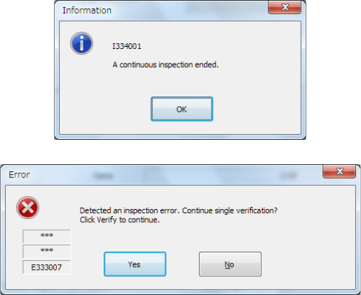
When the system finishes continuous inspection, it outputs the following message, and then
returns to the previous screen (“Continuous laser position inspection” screen).
If an error occurs during continuous inspection, the following message is output.
To inspect the next component, press the <Yes> button. The system restarts continuous
inspection.
To inspect a component that caused an error separately, press the <Yes> button.
You can inspect only a component that caused the inspection error.
(2) Component (to be inspected)
The component number (“No.”), the component type (“Type”), the packaging style
(“Package”), the nozzle number (“Nozzle No.”), the component name (“Name”), the bank
(“Bank”), the attachment hole (“Slot No.”) and the lane (“Lane No.”) are displayed here.
(3) Pickup position
The coordinates of a component pick-up position are displayed here.
(4) Inspected value
The laser height and component height to be checked are shown here.
• <Meas.> button
This button allows you to measure the laser position.
(See the next section for the laser position.)
(5) Result of inspection
After inspection, the result value appears in the “Result of inspection” column.
1) Status
OK : he centering operation is done successfully.
Number : the system failed to center a component (each number indicates a code
number of the laser status).
2) Width, Length
The size of a component that was centered successfully appears here.
3) Angle
The angle of the component obtained when it is centered appears here.
Part 1 Basic Operation Chapter 2 Production
2-127
Interrupting the continuous laser position inspection
To terminate the continuous laser position inspection forcibly, press the <STOP> switch. The
following message is output on the screen.
To terminate the inspection, select the <Yes> button.
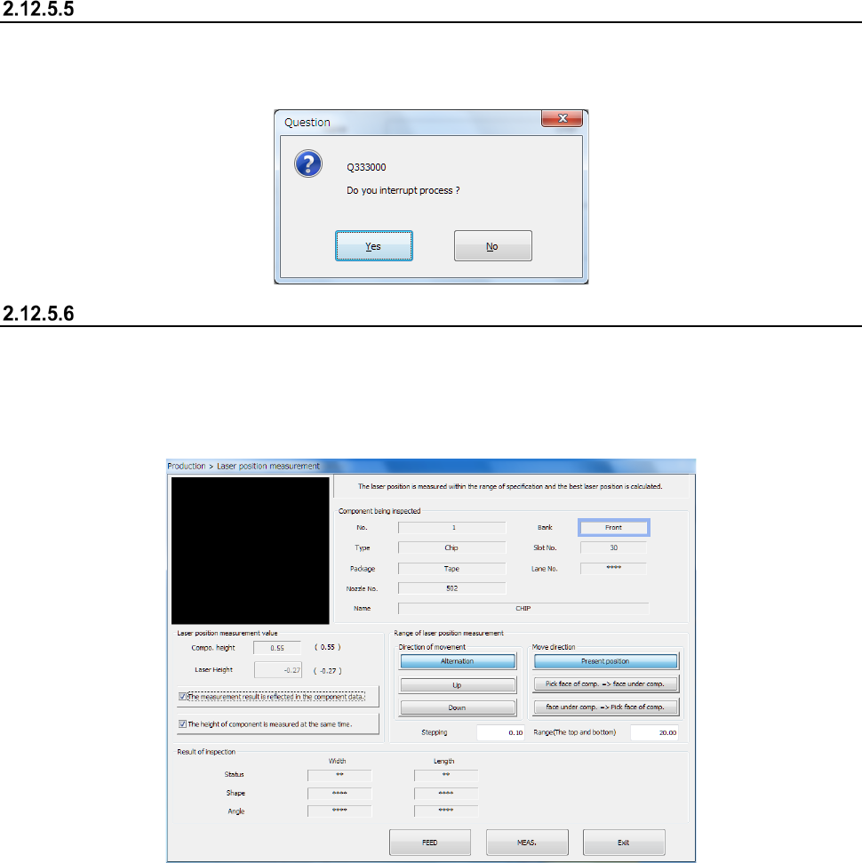
Laser position measurement
When you press the <Meas.> button on the screen for single laser position check, the following
“Laser position measurement” screen appears.
The laser position is repeatedly measured according to the conditions and in the direction that are
shown below, and the system sets the laser position that centered a component successfully as the
optimal laser position.
(1) Component being inspected
Data on the component being inspected appears here.
(2) Laser position measurement value
The data required to measure the laser height is shown here.
1) Compo. Height
The component height is displayed here.
2) Laser Height
You can change the laser height (position) as you like.
The value you set here is to be used as the “Present position” at start of the “Range of laser
position measurement.”
3) “The measurement result is reflected in the component data.
Put a check mark in this check box to apply the measured laser position to Component data
immediately.
4) “The height of component is measured at the same time.
When you put a check mark in this check box, the system measures the component height
before measuring the laser position. At the same time, the system calculates the laser
position automatically.