RS-1_instruction manual.pdf - 第764页
Part 2 D etaile d Descript ion of E ach Functi on Chapter 8 Machine Set up 8- 56 8.4.1 A xis movement display When you se lect [Head c ontrol] – [Free Mov e] tab, the following scr een appea rs. When you pres s the < …

Part 2 Detailed Description of Each Function Chapter 8 Machine Setup
8-55
8.4 Simple control
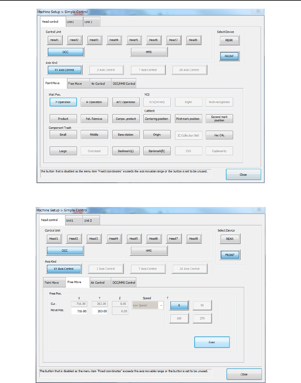
When you select “Simple control” from the Operation area of the Manual control, the Machine
setup, or the Self-calibration, the following main screen of the “Simple Control” opens.
The main screen is provided with the “Head control,” “Unit 1” and “Unit 2” tabs. The “Head
control” tab allows you to move a control unit specified with the <Select Device> button, the
<Control Unit> button, or the <Axis kind> button, control air of a head nozzle, control the OCC
lighting, and/or control the HMS sensor.
The “Unit 1” tab permits controlling the ATC, support table, cover lock, and conveyor.
The “Unit 2” tab permits MTS control.
Part 2 Detailed Description of Each Function Chapter 8 Machine Setup
8-56
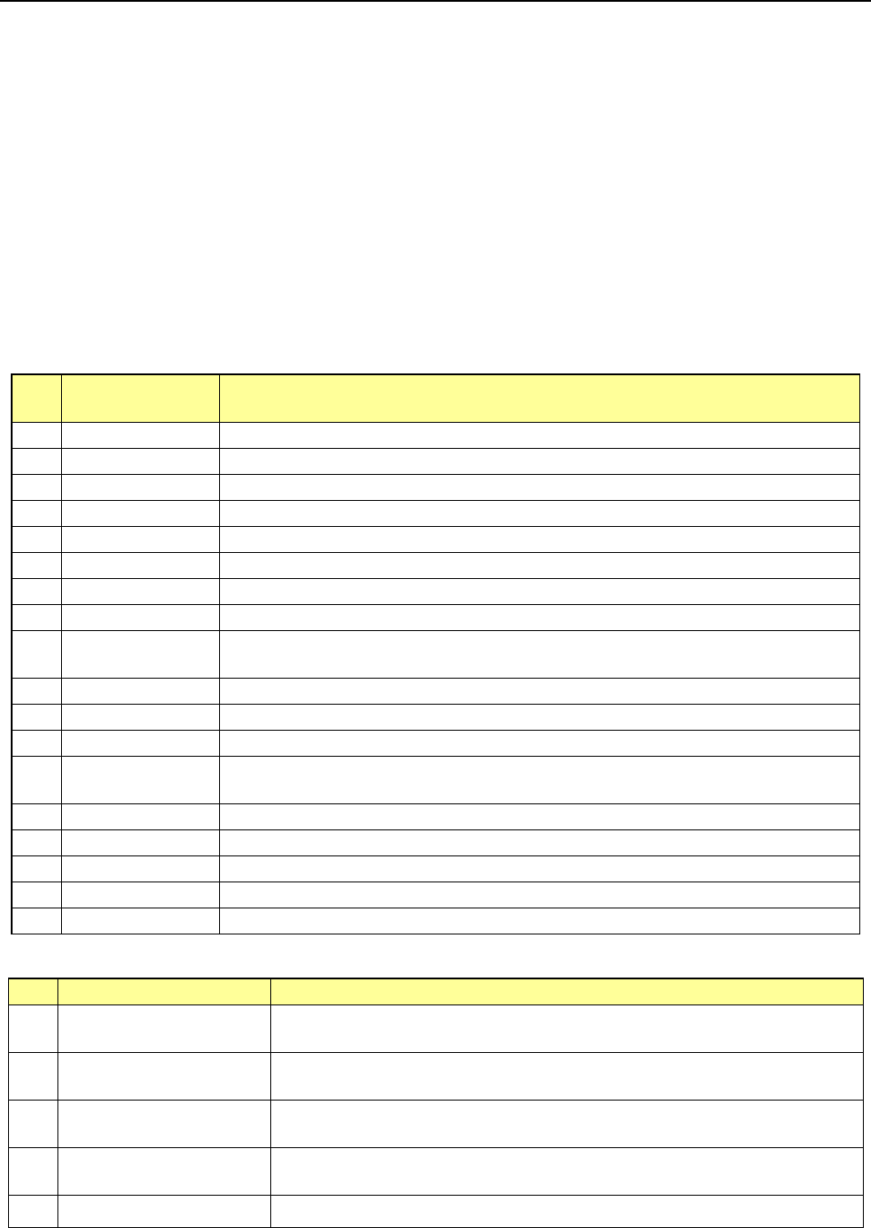
8.4.1 Axis movement display
When you select [Head control] – [Free Move] tab, the following screen appears.
When you press the <Exec> button, axis movement is performed up to the movement
coordinates of “Free Move” according to the control unit reference and specified speed.
Part 2 Detailed Description of Each Function Chapter 8 Machine Setup
8-57
8.4.2 Moving the axis
(1) XY Axis Control
You can control each unit in the XY direction in the following way. When you select the <XY
Axis Control> button from the “Axis Kind” group displayed on the main screen, you can move
the selected unit in the XY direction.
* When the VCS, CVS, SOT direction inspect unit and IC collection belt setting are
enabled, control unit can be selected.
* When the simple control screen is started from “Head nozzle condition”, only the following
items can be operated.
- Control unit: Select each of Heads 1 to 8, OCC, and HMS.
- XY axis control: Wait position, component reject position, VCS position, mark position,
unit position, and optional coordinates
- Z-axis control: Only the head is operated. “Wait, laser, XY movement, reference, nozzle
replacement, VCS, CVS and Coplanarity” height, and optional coordinates
- XY Axis Control (Control Unit: OCC, head, and HMS)
No.
Movement
position item
Details of item
1 F Operation Moves the head to the waiting position at the time of operation on the front side.
2
R Operation
Moves the head to the waiting position at the time of operation on the rear side.
3 ATC operation Moves the head to the waiting position at the time of ATC operation.
4
Production
Moves at production based on the specified control unit.
5 Nzl. Remove Moves to nozzle removal based on the specified control unit.
6
Compo. protect
Moves at temporary stop of component protection based on the specified control unit.
7 Centering position Moves to the centering position of CAL block based on the specified control unit.
8
First mark position
Moves to the first mark of CAL block based on the specified control unit.
9
Second mark
position
Moves to the second mark of CAL block based on the specified control unit.
10
Bare station
Moves to the pair station position based on the specified control unit.
11 Origin Moves to the coordinates of the home based on OCC.
12
Vac CAL
Moves to the vacuum CAL unit position based on the specified control unit.
13 Bank mark (L/R)
Moves to the feeder bank mark recognizing position (movable range) based on the
specified control unit.
14
IC Collection Belt
Moves to the IC collection belt position based on the specified control unit.
15 CVS Moves to the CVC position based on the specified control unit.
16
Coplanarity
Moves to the coplanarity position based on the specified control unit.
17 Bankmark (L) Moves to the bank mark (L) of the selected device based on the specified control unit.
18
Bankmark (R)
Moves to the bank mark (R) of the selected device based on the specified control unit.
- XY Axis Control (Control Unit: Head 1-8)
No.
Movement position item
Details of item
1 Component Trash (Small)
Moves to the small-size component reject position based on the
specified control
unit.
2 Component Trash (Middle)
Moves to the medium-size component reject position based on the specified
control unit.
3 Component Trash (Large)
Moves to the large-size component reject position based on the specified control
head.
4 VCS (Left / Right)
Moves to the position of VCS attached to the mounter based on the specified
control head.
5 Multi-recognition
Moves to the multi-recognition position based on the specified control head.