RS-1_instruction manual.pdf - 第72页
Part 1 B asic O peration Chapter 1 Overv iew of the Machine 1- 54 Display device and D ata input dev ices Display device (touch panel) T he display device used i n the mach ine is a color l iquid crystal display (LCD) eq…
Part 1 Basic Operation Chapter 1 Overview of the Machine
1-53
Basic Operations
Screen organization
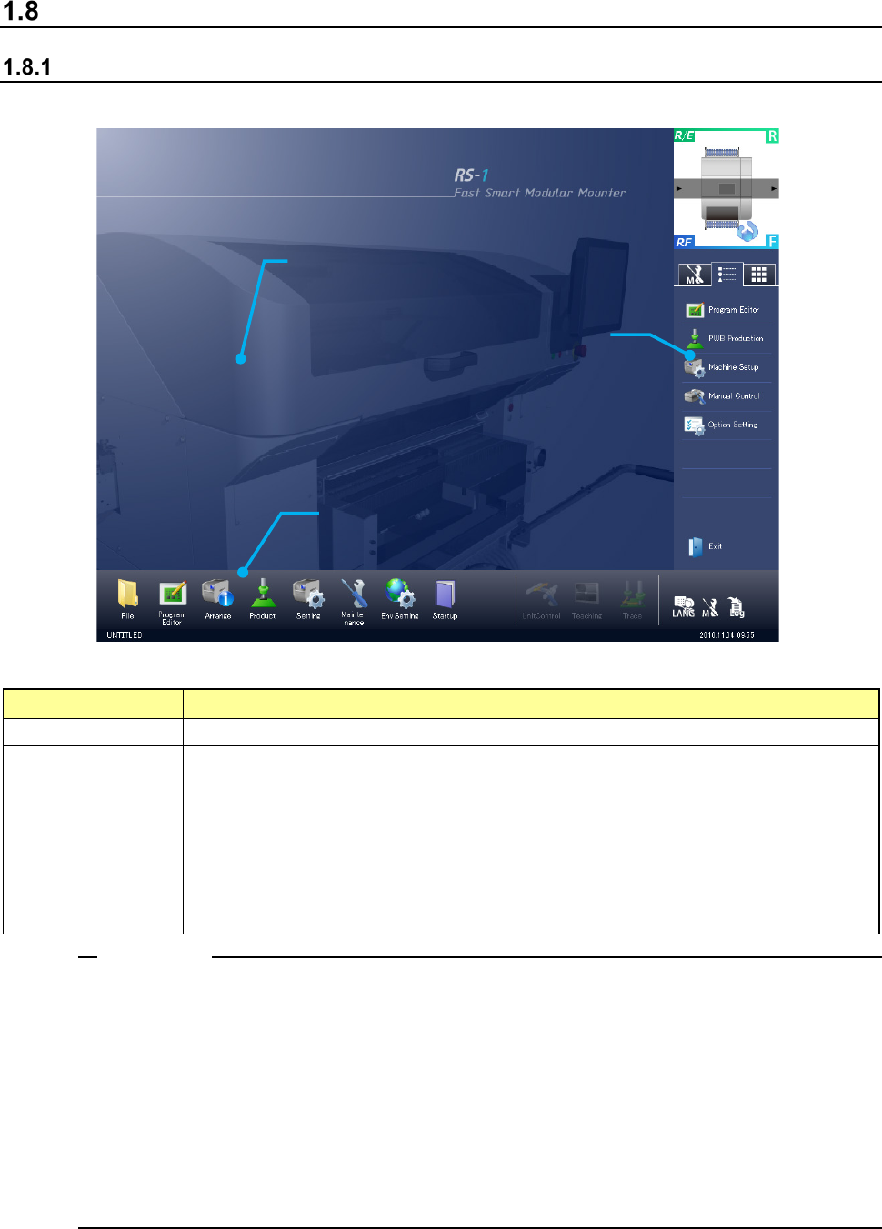
(1) Desktop screen
Screen components and overview of their functions
Element
Description
① Application area Each application screen is displayed here.
② Operation area
You can invoke a command to be used on the desktop screen or with each application
program.
You can invoke the typical functions that can be executed with each application program also.
Several functions such as a function for switching the displayed language are provided.
The production program name and the current time are displayed here.
③ Information area
A simple asynchronous event and maintenance information are displayed here.
When you switch the tabs, you can display the maintenance menu, the application shortcut
keys and the software keyboard here also.
1. When you use the Operating System (OS) other than the English edition (that is, Japanese
edition or Chinese edition) to switch the used language with the [Language Selection]
command in order to display English, a part of or the entire screen may not be switched to the
English screen and the screen may be displayed in the language used in the OS.
<Examples of the screens not changing the language to English>
File management and System menu
2. When you set data that can be set in Japanese (Chinese) such as the PWB ID, component
name and comment on a component in Japanese (Chinese), the screen may not be displayed
correctly when you switch the screen with the [Language Selection] command.
Notes:
①
Application area
③ Information area
② Operation area
Part 1 Basic Operation Chapter 1 Overview of the Machine
1-54
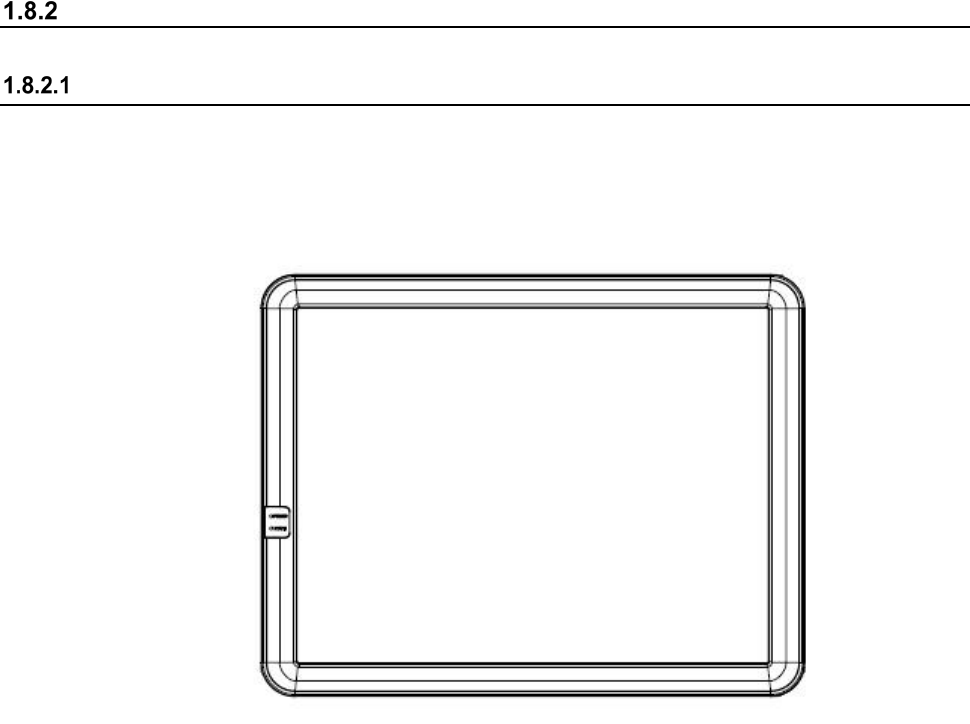
Display device and Data input devices
Display device (touch panel)
The display device used in the machine is a color liquid crystal display (LCD) equipped with touch
panel operating functions. (Standard XGA 1024×768 dots) The rear side display is provided as
an optional device.
Part 1 Basic Operation Chapter 1 Overview of the Machine
1-55
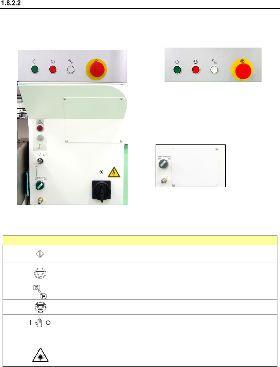
Operation panel
You can use the operation panel of the machine main unit to control the machine.
Front panel Rear panel
Switches and their functions
No.
Switch
Name
Function
1
Start
This is the switch for start.
Use to start an actual production run.
2
Pause/Stop
Use this switch to terminate PWB production or another operation.
Press the switch once to put the production run in a pause status.
Press the switch the second time to stop the production run.
3
Operation
change
Switches the side on which the switches can be operated, <FRONT> or
<REAR>.
4
Emergency
This is the switch for emergency stop. Use this switch to immediately stop
the machine when it malfunctions or when it may pose risks to your safety.
5
Maintenance
Key
Switches between a production mode (a key inserted vertically) and
a maintenance mode (a key inserted horizontally).
6
Feeder Bank
Switch
Feeder Bank
Switch
T Up-and-down switch of the feeder bank (available when a feeder
exchange trolley is used).
7
Caution Lamp
Lights while the coplanarity unit (option) is radiating laser. (As an
exception, it lights when the main unit of the mounter starts up, but
the unit does not radiate any laser in this case.)
① ②
③
④
⑥
⑤
⑦
①
②
③
④
⑥
⑤
⑦