RS-1_instruction manual.pdf - 第577页
Part 1 B asic O peration Chapter 4 Cr eating a Produc tion Progra m 4- 242 (2) E xecut ing measur ement of the height of a PWB on which c omponent s are plac ed Immediate ly after you pr ess the <EXEC> but ton, th …
Part 1 Basic Operation Chapter 4 Creating a Production Program
4-241
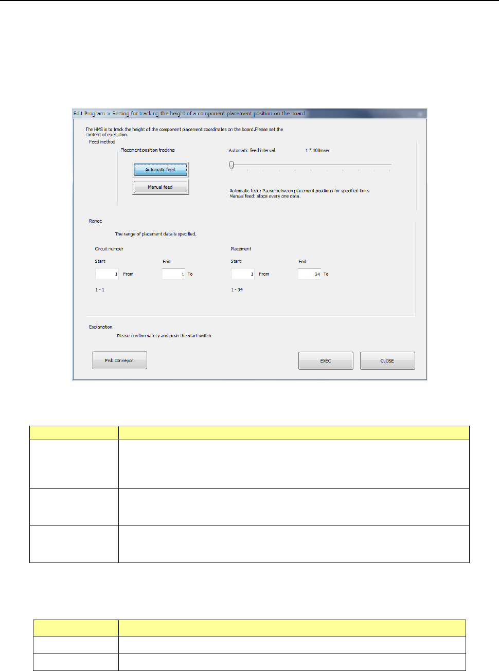
4.5.7.2 PWB Height
This command measures the height of the surface of a PWB at a component placement position
with the HMS.
(1) Setting for tracking the height of a PWB on which components are placed
When you select the [PWB Height] command from the “Meas/Insp” menu, the following “Setting for
tracking the height of a component placement position on the board” dialog box appears on the
screen.
1) Feed method
Set the camera operation to be performed during measurement.
Menu item
Overview
Automatic feed
This button measures the height of a PWB at component placement positions one
by one at regular intervals.
The camera stops for the period of time set with the “Auto feed interval,” and then
the camera moves to the next position after lapse of this time.
Manual feed
The camera stops without moving to the next position until the user operates the
system after the system measures the height of a PWB at the component
placement position.
Auto feed interval
This menu item adjusts the stop interval of the camera when you select the
<Automatic feed> button.
You can set the interval in the range of 10 msec to 5 seconds.
2) Range
Specify the tracking range of the Placement data. By default, all placement positions are to
be tracked.
Menu item Overview
Circuit number Specifies the measurement range with the circuit numbers.
Placement Specifies the measurement range with the placement positions.
After setting the range, press the <EXEC> button to start measurement.
Part 1 Basic Operation Chapter 4 Creating a Production Program
4-242
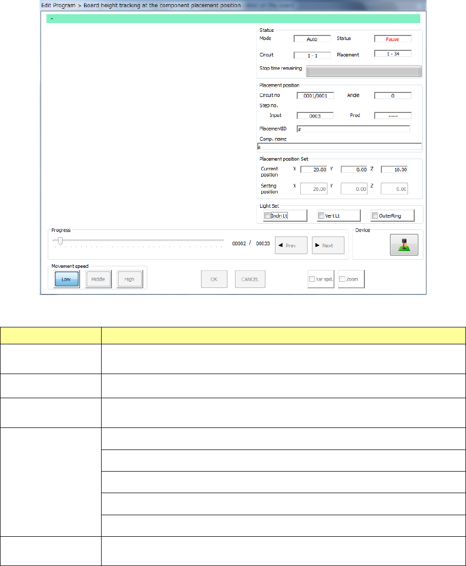
(2) Executing measurement of the height of a PWB on which components are placed
Immediately after you press the <EXEC> button, the system performs BOC alignment operation
before measurement if BOC marks are set in a production program. (The system recognizes
BOC marks on all circuits.)
While the system is measuring the height of a PWB on which components are placed, the
following screen appears.
1) Status
Menu item Overview
Mode
The feeding method specified with the menu item “Feed method,” “Auto” or
“Manual,” is displayed here.
Circuit The range of circuits whose heights are to be measured is displayed here.
Placement
The range of component placement positions at which the height is to be
measured is displayed here.
Status
“Moving” indicates that the axis is moving.
“Pause” indicates that the axis stops temporarily in Automatic Feed mode.
“Stop” indicates that the axis stops manually or intentionally.
“Axis esc” indicates that the axis is moving to the safety position.
“Mark recog” indicates that the system is recognizing an IC mark.
Stop time
remaining
The progress bar shows the remaining stop time in Automatic Feed mode.
Part 1 Basic Operation Chapter 4 Creating a Production Program
4-243
2) Placement position
Menu item Overview
Circuit no Circuit being measured/Total number of circuits
Angle Component placement angle being measured
Step no. Placement data number being measured
Placement ID Placement ID being measured
Comp. name Name of a component being measured
3) Placement position set
The current measured coordinates are displayed in the “Current position” fields, while the
coordinates set on the “Placement” data screen are displayed in the “Setting position” fields.
4) Light Set
Select OCC lighting that is used to display the placement point.
5) Progress
When you move this slider as desired while the system stops, it can move the tracking
position to the previous placement position or the next one.
CAUTION
To avoid a risk of injury, do not put your hands inside the machine nor
move your face or head close the machine while you are operating the
machine.