RS-1_instruction manual.pdf - 第137页
Part 1 B asic O peration Chapter 2 Pr oduction 2- 26 Adjusting the shape clamp reference <How to chan ge the posit ion> (1) S elect t he “Product ” butto n from the m ain menu, t he [Support ] comma nd, and then t …
Part 1 Basic Operation Chapter 2 Production
2-25
Adjusting the PWB transport rail width
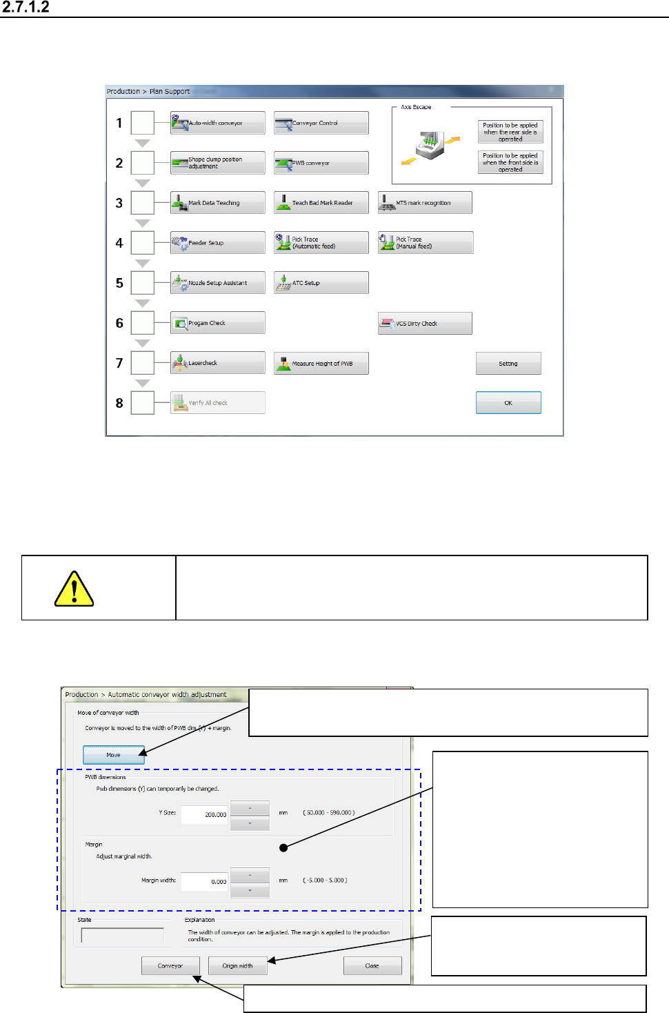
<How to adjustment the rail width on the “Automatic conveyor width adjustment” screen>
(1) Select the “Product” button from the main menu, the [Support] command, and then the [Plan
support] command.
(2) Adjust the conveyor width.
When you press the <Auto-width conveyor> button, the “Automatic conveyor width adjustment”
screen appears.
The operation for “Automatic board width adjustment” varies depending on the conveyor lane
configuration, a single-lane conveyor or a dual-lane conveyor.
CAUTION
When you click the <Move> button with following the instruction below,
the conveyor starts operating. Before clicking this button, be sure to
check to see if there is no obstacle in the conveyor movable section.
1) Automatic board width adjustment
③ Select the <Move> button to adjust the conveyor width.
The motor rotates and the machine adjusts the conveyor width.
④ Check to see if a PWB is transported with the conveyor smoothly.
②
Enter the desired value into the
“Y Size” field and the “Margin
width” field respectively.
(If the conveyor width is not
appropriate for a board to be
transported, be sure to enter
the appropriate value into the
“Margin width” (the allowable
input value range: from - 0.5
mm to 0.5 mm).
①
Select the <Origin width>
button to return the conveyor to
its origin.
Part 1 Basic Operation Chapter 2 Production
2-26
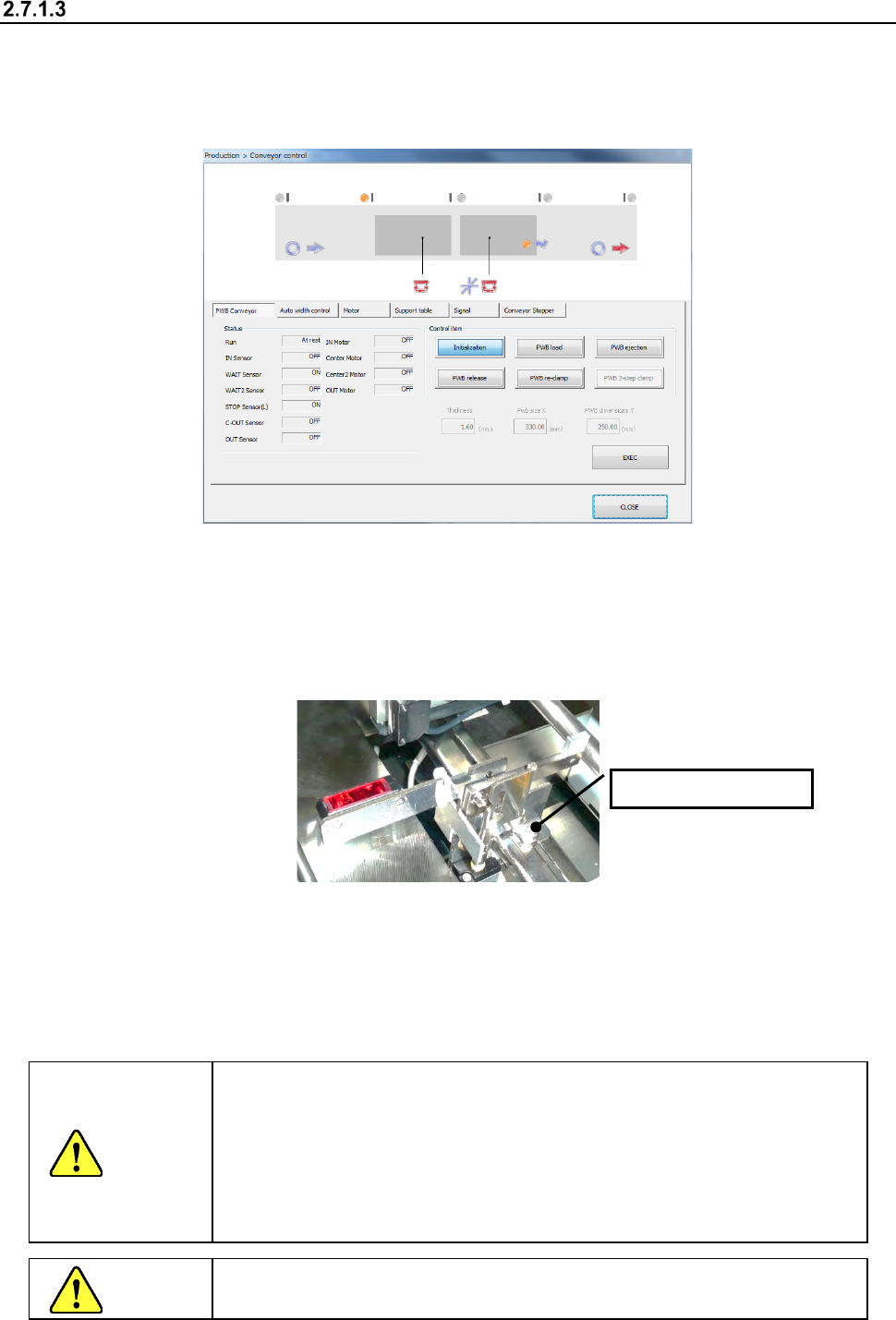
Adjusting the shape clamp reference
<How to change the position>
(1) Select the “Product” button from the main menu, the [Support] command, and then the [Plan
support] command.
When you press the <Conveyor control> button, the “Conveyor control” screen appears.
(2) Turn the stopper ON.
Select “Conveyor Stopper” and press the <ON> button.
(3) Push the PWB to be produced until it comes in contact with the stopper.
If the PWB has a notch, etc. at the contact point and the contact status is unstable, make
adjustment by loosening the two screws at the root of the stopper and moving the stopper by
hand.
(4) Arrange the support pins.
Place the support pins on the support table suitably according to the PWB to be produced. Placing
support pins under a QFP and other components which require high precision of placement
improves the precision.
(5) After adjustment, press the <CLOSE> button on the “Conveyor control” screen to finish
conveyor control.
CAUTION
The shape clamp reference position is the origin (i.e. a reference point) of
the PWB coordinates of the program data.
Consequently, when the stopper position has been adjusted, make sure
to reset it following Section 2.7.1.4 “Adjusting the shape clamp reference
position”.
The PWB origin can be changed by the “PWB data” in the production
program. (See Section 4.3.3. “PWB data” of Chapter 4).
CAUTION
While the machine is operating, NEVER insert your hand, head, etc.
inside the machine.
Loosen the screw.
Part 1 Basic Operation Chapter 2 Production
2-27
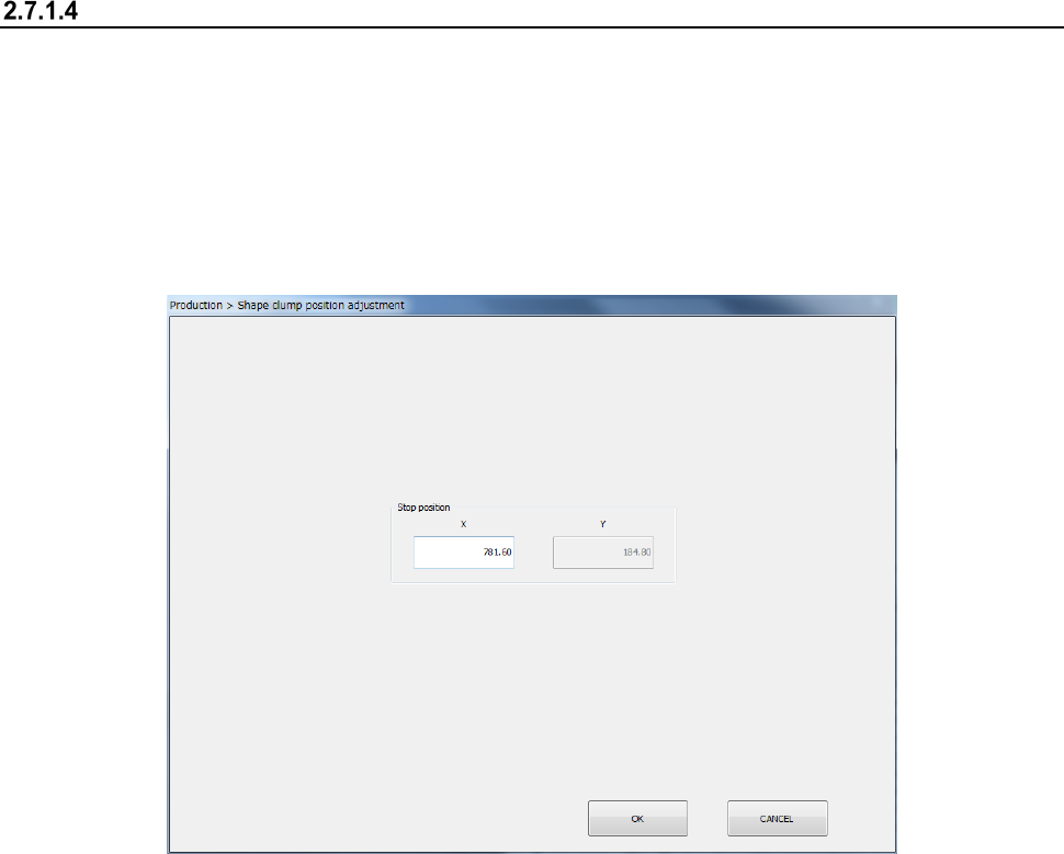
Adjusting the shape clamp reference position
When the stopper position has been adjusted, it is necessary to reset the shape clamp reference
position as shown below.
<How to change the position>
(1) Select the “Product” button from the main menu, the [Support] command, and then the [Plan
support] command.
When you press the <Shape clamp position adjustment> button, the “Shape clamp position
adjustment” screen appears.
- See Section 8.3.3.3 “Shape clamp position adjustment” for detailed setup procedures.