RS-1_instruction manual.pdf - 第478页
Part 1 B asic O peration Chapter 4 Cr eating a Produc tion Progra m 4- 143 4.4.2 .3 Feeder layout The [Feeder L ayout] command d isplays the f eeder l ayout specif ied on the “ Pick ” data screen graphica lly , and it al…
Part 1 Basic Operation Chapter 4 Creating a Production Program
4-142
4.4.2.2 Nozzle layout
The [Nozzle layout] command displays the nozzles assigned to each station with the Optimization
function.
When you specify “Auto arrange nozzles” in the “Nozzles” field of the “Assignments” option screen,
check the result on the following screen, and set nozzles so that the nozzles can be assigned in
the same way specified on the “Machine setup” menu.
When you select the [Optimization] – [Nozzle layout] commands, the “Nozzle layout” screen
appears.
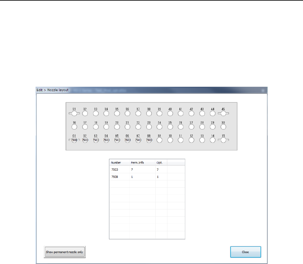
The following “Nozzle layout” screen appears.
a) Nozzle layout diagram
The nozzle layout output with the Optimization function is displayed here.
If any nozzle not shown on this nozzle layout is set on the “Machine Setup” screen, it is
indicated in red on the screen.
b) ATC Device
Select the position of the ATC to be displayed, the front or the rear.
c) Nozzle information
Number: Nozzle numbers are displayed here.
Perm. Info: The number of nozzles set on the “Machine Setup” screen is displayed here.
Opt.: The number of nozzles output with the Optimization function is displayed here.
d) Show permanent nozzle only
This button switches the “Nozzle layout” screen to the screen indicating the nozzle layout
set on the “Machine Setup” screen.
Part 1 Basic Operation Chapter 4 Creating a Production Program
4-143
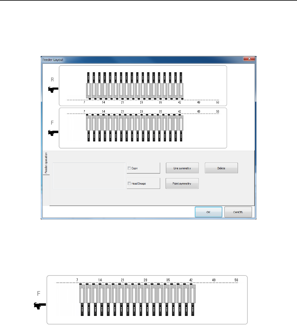
4.4.2.3 Feeder layout
The [Feeder Layout] command displays the feeder layout specified on the “Pick” data screen
graphically, and it allows you to check feeders with your eyes and/or handle the feeder layout.
(1) “Feeder layout” screen
When you select the [View]-[Feeder layout] commands from the menu, the following “Feeder
Layout” screen appears on the screen.
1) Bank image
On the “Feeder Layout” screen, the feeder layout specified on the “List” screen of the “Pick”
data is shown graphically.
For the electric bank (RF) or the electric bank (RF/EF), the image shown below is
displayed.
Part 1 Basic Operation Chapter 4 Creating a Production Program
4-144
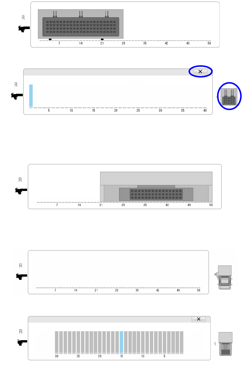
When a holder is selected as a component supply unit, an image of a tray is displayed as
shown below.
When you touch the displayed image of a tray, its enlarged image is displayed on the
screen.
To return to the original image display, touch the [×] button or the tray image displayed on
the right side of the screen.
See “(3) Copying/moving/deleting a feeder” of "4.4.2.3 Feeder layout" for how to operate it.
When a TR8SR is selected as a component supply device, the feeder layout is displayed
with the image of the TR8SR as shown below.
When you touch the displayed TR8SR image, the enlarged TR8SR image is displayed on
the screen.
When a MTC is selected as a component supply device, the feeder layout is displayed with
the image of the MTC as shown below.
When you touch the displayed MTC image, the enlarged MTC image is displayed on the
screen.
To return to the original TR8SR image screen, touch “×” or the MTC/MTS image displayed
on the right side of the screen.