RS-1_instruction manual.pdf - 第124页
Part 1 B asic O peration Chapter 2 Pr oduction 2- 13 “EVENT VI EW” scree n When you op en the safety cover , when you push the Emergency Stop s witch or when the m achine detects a serv o driver alarm of each ax i s, the…
Part 1 Basic Operation Chapter 2 Production
2-12
2) Manual way
If any head is detected in the “Detected Head” column, return the nozzles “manually.”
CAUTION
Be sure to check to see if the head stops completely before taking out
a nozzle and return it manually.
As described before, this method allows you to move a head to the position where an
operator can remove a nozzle easily, and take out a nozzle from the head to return it into the
ATC.
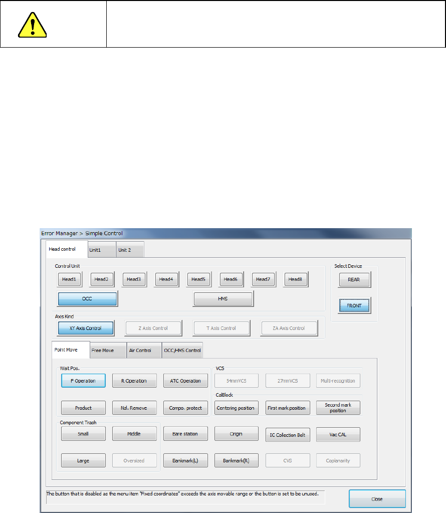
Select the <Simple Axis Control> button to move a head or open/close the ATC.
When you click the <Simple Axis Control> button on the “Nozzle On Head Information”
screen, the following screen appears.
The origins of the XY coordinates (0. 0) are the left edge on the front side where the
operation panel is located.
The origin of the Z axis (0) is the height of a board, and the up direction is “+,” and the down
direction is “-.”
The “Axis Move” tab invoked from the “Simple Control” screen provides the menu items “XY
Axis Control” and “Z Axis Control.” They allow you to control the axes operation. In the
same manner, the menu item “ATC Control” on the “Unit” tab allows you to open/close the
ATC.
See Section 9.7 “Simple Control” for details of these operations.
Part 1 Basic Operation Chapter 2 Production
2-13
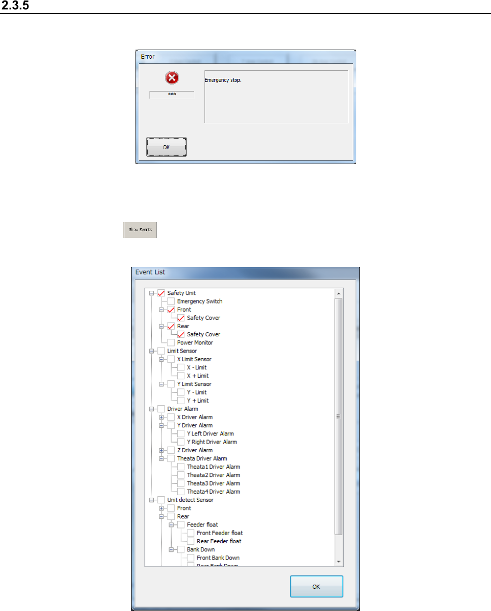
“EVENT VIEW” screen
When you open the safety cover, when you push the Emergency Stop switch or when the machine
detects a servo driver alarm of each axis, the following screen appears.
If two or more events occur at the same time, the event whose priority is highest is displayed as an
error.
When you press the button, the events that have occurred are displayed in the hierarchical
structure. A check mark appears in the front of the events that have occurred.
Part 1 Basic Operation Chapter 2 Production
2-14
2.4 Warming Up
Warm up the machine mainly after holidays or in cold climates immediately after you turn on the
machine.
The time required to warm up the machine is approximately 10 minutes, but varies depending on
the surrounding conditions.
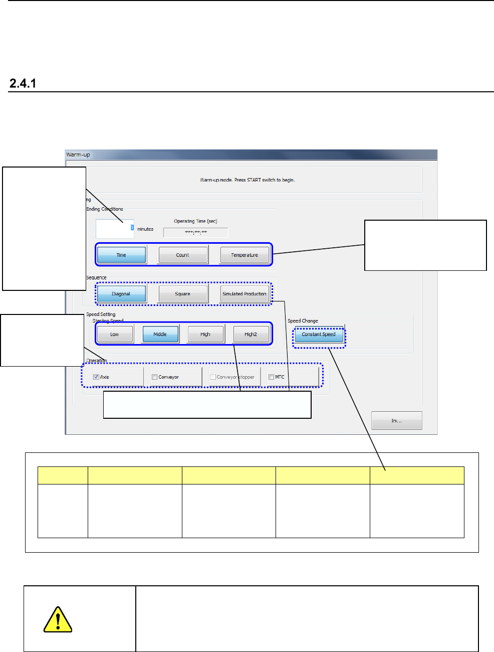
Initial screen
When you select the "Product" button from the menu displayed on the main menu, then the
[Warm-up] command, the following warm-up initial window appears on the screen so that you can
set the warming-up conditions.
Part of the display changes depending on user groups as follows:
Item Sequence Station Speed Speed Change
Display Hidden for an
operator whose user
level is lower than
“Service Engineer.”
Hidden for an
operator whose user
level is lower than
“Service Engineer.”
Grayed out for
groups lower than
“Service Engineer.”
Hidden for an
operator whose user
level is lower than
“Service Engineer.”
When you press the <START> button, the machine starts warming up.
WARNING
When you press the <START> switch, the axis starts moving to warm
up. Be sure to check to see if any person is not operating the inside
of the machine before pressing the <START> switch. Keep your
hands, face or head away from the machine while the machine is
warming up to avoid injuries
Select the conditions for
finishing the warming-up
operation.
Enter the time
the machine
finishes warming
up, the number
of times it has to
warm up, or the
temperature at
which it finishes
warming up.
You can select
which part to be
warmed up.
Settings restricted depending on user groups