RS-1_instruction manual.pdf - 第910页
Part 2 D etaile d Descript ion of E ach Functi on Chapter 12 Handling th e Optional Device s 12 - 26 12.3.8 Removing the stopper (TR5 SNX/TR5DNX) You have to rem ove the st opper from an MTS o ther than a TR8SR when c on…
Part 2 Detailed Description of Each Function Chapter 12 Handling the Optional Devices
12-25
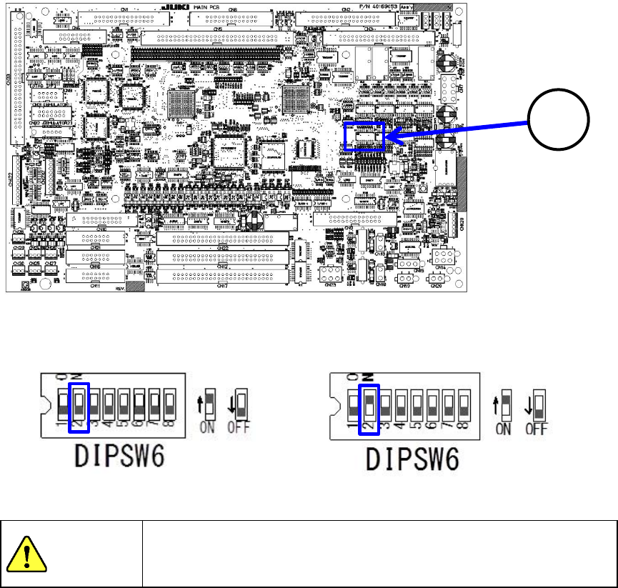
When you set the DIP SW 6-2 located at the position ③ of the MAIN board to ON, the
TR5SNX/TR5DNX that has been remodeled and whose software has been upgraded can be used
with the RS-1/1R. When you set the DIP SW 6-2 to OFF, the MTS can be connected to a machine
model other than an RS-1/1R with which the MTS can be used.
Machine model the MTS is connected to:
Other than an RS-1/1R
Machine model the MTS is connected to:
RS-1/1R
To avoid any accident caused by sudden activation of the machine,
turn off the power.
3
CAUTION
Part 2 Detailed Description of Each Function Chapter 12 Handling the Optional Devices
12-26
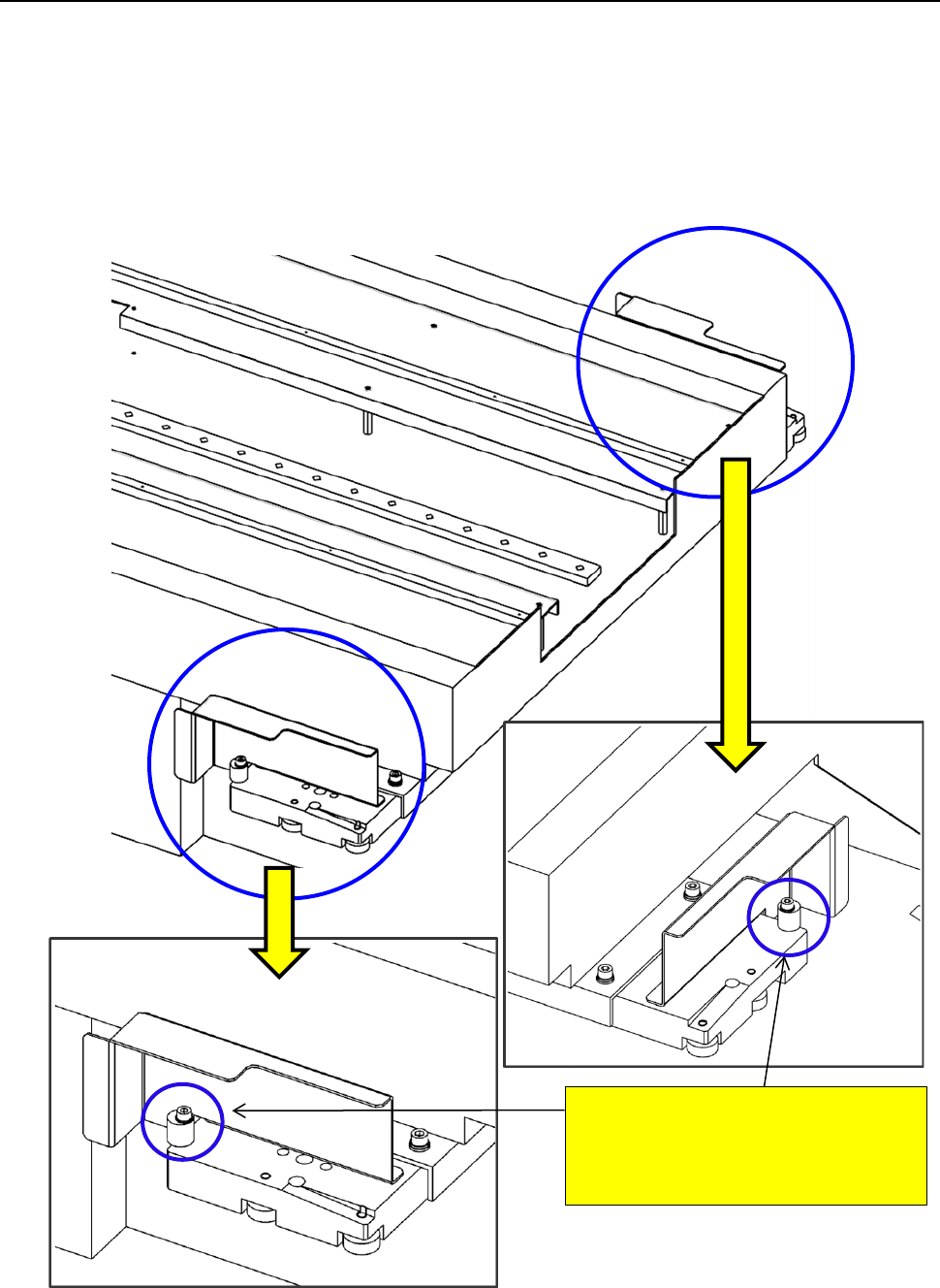
12.3.8 Removing the stopper (TR5SNX/TR5DNX)
You have to remove the stopper from an MTS other than a TR8SR when connecting it to an
RS-1/1R.
Since the stopper is attached on the MTS at the factory, remove it from the MTS when connecting it
to the RS-1/1R. When connecting it to a machine other than an RS-1/1R, attach the stopper on the
MTS.
To use with the RS-1/1R a TR5SNX/TR5DNX that was used in another machine model, follow the
instructions below only after remodeling the MTS and upgrading its software.
<<Stopper>>
RS-1/1R: Remove the stopper.
Machine model other than
an RS-1/1R: Attach the stopper.
Part 2 Detailed Description of Each Function Chapter 12 Handling the Optional Devices
12-27
12.4 Handling the IC Collection Belt
12.4.1 Specifications
Components
Types: QFP, SOP, PLCC, etc. (Components using image recognition device)
Sizes: □10 to □50mm,1.0 to 6.0 mm
Collection
number of IC
9 to 31 pcs (depending on the maximum size of IC to be used.)
Feeding mount of
belt
15 to 55 mm (by 5 mm)
(Set the rotary switch to manual mode according to the maximum size of IC)
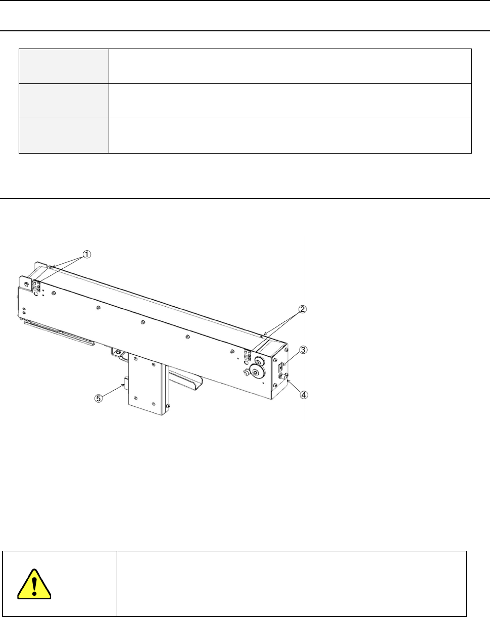
12.4.2 Configuration and parts identification of the IC collection belt
IC collection belt for electric bank
- This unit allows the machine to collect components which are not placed on a board for
some reason without damaging them after the components are recognized with the VCS.
• Components which are placed on the component sensor ① from the head are fed
sequentially at the pitch selected with the rotary switch ③.
• When the belt is full of components and the Stop sensor ② detects a component, the
main unit pauses and displays the message on the screen.
CAUTION
- To prevent your body from injury and to avoid damage to the machine, check to
see if the machine main unit stops completely before opening the safety cover to
remove a component from the IC collection belt.
- If you remove components from the IC collection belt still attached on the feeder
bank, always keep in close touch with other operators.
① Component sensor
② Stop sensor
③ IC size setting rotary switch
④ Reset switch
⑤ Power plug