RS-1_instruction manual.pdf - 第994页
Part 2 D etaile d Descript ion of E ach Functi on Chapter 12 Handling th e Optional Device s 12 - 110 12.16 Manual Noz zle Att achm ent Functi on 12.16.1 Overv iew When you use a c ustom ized nozzl e that cannot b e set …
Part 2 Detailed Description of Each Function Chapter 12 Handling the Optional Devices
12-109
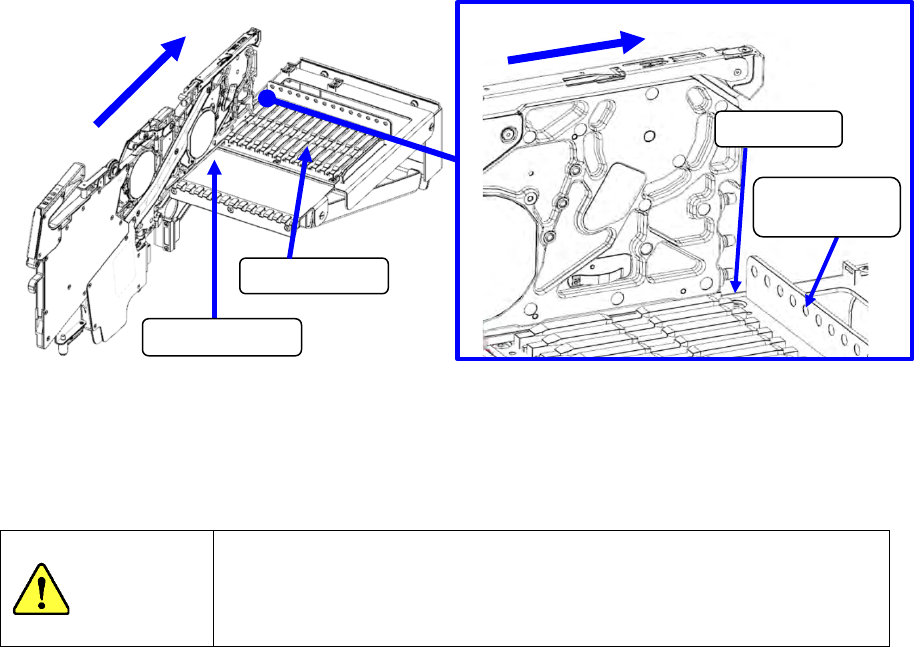
(3) Operate the lock release lever of the feeder and clamp the feeder in the position where the
guide pin strikes against the positioning plate. To supply electric power, mount the feeder on
the left-end lane.
(4) Set a tape on the RF series electric feeder. (Refer to the Instruction Manual of each RF
series Electric tape feeder for how to set a tape onto it.)
CAUTION
When opening or storing a tape set unit, be careful to prevent a hand
from being caught between the movable parts.
If you work around the machine when the tape set unit is used, be
careful not to hit your head or hand on the machine.
Guide rail
Slide rail
Guide pin
Positioning
plate
Part 2 Detailed Description of Each Function Chapter 12 Handling the Optional Devices
12-110
12.16 Manual Nozzle Attachment Function
12.16.1 Overview
When you use a customized nozzle that cannot be set on the ATC, you can manually attach the
nozzle on a head without using the ATC. (Manual nozzle attachment function)
To use this manual nozzle attachment function, the machine is set exclusively to allow a nozzle to
be attached on a head manually, and it cannot replace nozzles with using any ATC.
When you attach a nozzle on a head manually, the machine uses the nozzle that is attached on a
head manually before PWB production to produce PWBs without replacing any nozzles during
production.
12.16.2 Preparation
To use the manual nozzle attachment function, set the Z-axis of the heads adjacent to the head on
which a nozzle is to be attached manually so that it cannot be used. Fix the head whose Z-axis is
set not to be used with following the description of the Chapter 8 “Machine Setup.”
WARNING
To avoid any accident caused by sudden activation of the machine,
turn off the power.
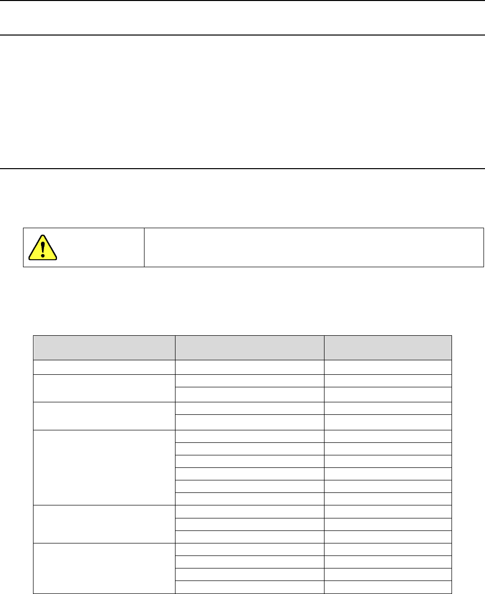
Select a head on which you are to attach a nozzle manually with taking into consideration
interference of the nozzles manually attached on heads and the size of components to be used for
production.
Component size
Head on which a nozzle is
to be attached manually
Unused head
□
7.0 mm or less
1,2,3,4,5,6,7,8
None
More than
□
7.0 mm but
□
14.9 mm or less
1,3,5,7
2,4,6,8
2,4,6,8
1,3,5,7
More than
□
14.9 mm but
□
20.0 mm or less
1,4,7
2,3,5,6,8
2,5,8
1,3,4,6,7
More than □
20.0 mm but
□23.4 mm or less
2,5
1,3,4,6,7,8
3,6
1,2,4,5,7,8
4,7
1,2,3,5,6,8
2,6
1,3,4,5,7,8
3,7
1,2,4,5,6,8
2,7
1,3,4,5,6,8
More than □
31.9 mm but
□35.0 mm or less
2,6
1,3,4,5,7,8
3,7
1,2,4,5,6,8
2,7
1,3,4,5,6,8
More than □35.0 mm
3
1,2,4,5,6,7,8
4
1,2,3,5,6,7,8
5
1,2,3,4,6,7,8
6
1,2,3,4,5,7,8
Note: When you use a nozzle that is to be attached on a head manually and whose shape is
designed for a component that is to be recognized with a VCS, you have to set an unused
head depending on the outer dimension of the nozzle.
Part 2 Detailed Description of Each Function Chapter 12 Handling the Optional Devices
12-111
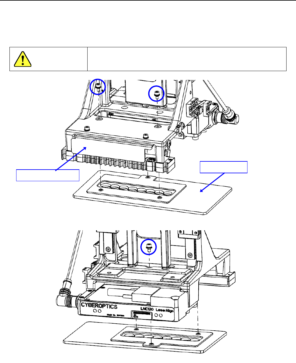
12.16.2.1 Removing a diffuser (only when you select a nozzle 7111)
If you use the manual nozzle attachment function when a nozzle 7111 (40211594) is selected,
remove three fixing screws shown in the figure below, and then remove the diffuser from the
LNC120 sensor.
If you do not remove the diffuser, select a nozzle 7111L (40249881).
WARNING
To avoid any accident caused by sudden activation of the
machine, turn off the power.
Diffuser
LNC120 sensor