RS-1_instruction manual.pdf - 第415页
Part 1 B asic O peration Chapter 4 Cr eating a Produc tion Progra m 4- 80 (8) Inspection 3 This tab she et allows you to set the m enu item “Me asure P WB Surface H eight ” and “ Height check after plac ing .” The system…
Part 1 Basic Operation Chapter 4 Creating a Production Program
4-79
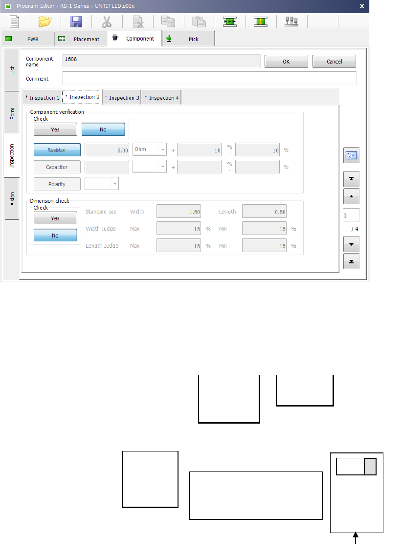
(7) Inspection 2
This tab sheet allows you to set the following items: “Component verification” and “Dimension
check.”
1) Component verification (option)
This item is mainly used to check a component setting error. Select whether to verify a
component or not with the corresponding button, <Yes> or <No>.
When you select the <Resistor> button or the <Capacitor> button, enter the threshold value,
the unit and the lower/upper limit of the allowable error. Select the unit from the drop-down
list.
Ω
PF
KΩ
μF
MΩ
When you select the <Polarity> button, you can select the direction from the drop-down list.
Right
Top
Left
Bottom
2) Dimension check
Specify whether to perform a dimension check of a component or not with the corresponding
button, <Yes> or <No>.
Specify the length and the width of a component in the “Standard size” fields. Specify the
allowable maximum difference and the minimum difference between the values set in the
“Standard size” field and the value measured actually in the “Width Judge” fields and the
“Length Judge” fields in % respectively.
Main unit side
+
Set the direction of the positive
electrode viewed from the
component supply direction
(packaging style)
Tape feeder
Part 1 Basic Operation Chapter 4 Creating a Production Program
4-80
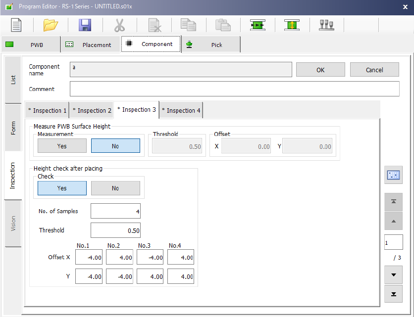
(8) Inspection 3
This tab sheet allows you to set the menu item “Measure PWB Surface Height” and “Height check
after placing.”
The system measures the height of the surface of a board at the component placement position to
correct the Z coordinate of the component placement position.
The measurement position is in the center (- point) of the component placement position.
1) Measurement
Specify whether to measure the height of the surface of a board on which a component is to
be placed with the corresponding button, <Yes> or <No>.
2) Threshold
Enter the value for determining whether the board warps or not based on the measurement
result.
3) Offset
Enter the offset from the component placement position to be measured.
When the measured value is within the range of a negative value set in the “Threshold” field
to a value set in the “Threshold” field, the system decides that it can place the component on
a board.
Part 1 Basic Operation Chapter 4 Creating a Production Program
4-81
2) Height check after placing
This function checks to see if a placed component equipped with a boss does not incline by
measuring the height of each of four corners of the component with the HMS after the
component is placed on a board.
When the result is between a negative value set as the “Threshold” and a positive value set as
the “Threshold,” the function decides that the component is placed on the board normally.
If the result exceeds this range, the production stops temporarily.
Setting item
Description
Check
Specify whether to check the component height.
No. of Samples
Specify how many positions are to be checked between 2 and 4.
Threshold
Specify a value for deciding that a component is placed on a
board normally.
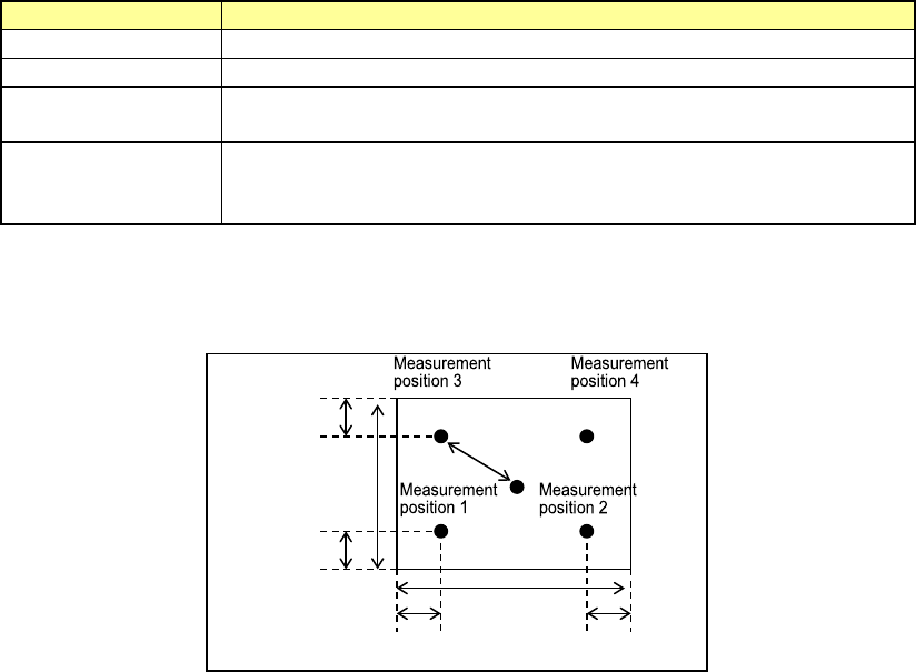
Offset X, Y
Specify where to check by offset values viewed from a positon at
which a component is placed. Specify measurement (check)
positions from the top, Position 1, 2, 3 and 4.
The figure below shows the relation between the offset value of each measurement position
and a positon to be checked.
Offset value
30 % of the
length
30 % of the width
30 % of the
length
30 % of the width