RS-1_instruction manual.pdf - 第352页
Part 1 B asic O peration Chapter 4 Cr eating a Produc tion Progra m 4- 17 1) P WB dim ensions Enter the dim ensions of the PWB inclu ding all circuits. 2) P WB la yout off set Enter the length f rom the PW B position ref…
Part 1 Basic Operation Chapter 4 Creating a Production Program
4-16
(3) Multi-plane matrix PWB
On a multi-plane PWB, two or more circuits of the same type are arranged.
There are two types of multi-plane PWBs: matrix circuit PWB and non-matrix circuit PWB.
The angles of all circuits are equal to one another, and the distance between two consecutive
circuits (pitch) is equal on a matrix circuit PWB. As Placement data, create data on one circuit
(called as “reference circuit”), as PWB data, enter information on the circuit arrangement (such as
the pitch between circuits and the number of circuits).
Pitch Y
Reference circuit
Fourth circuit
Second circuit
Third circuit
Pitch X
Origin of the reference circuit
Part 1 Basic Operation Chapter 4 Creating a Production Program
4-17
1) PWB dimensions
Enter the dimensions of the PWB including all circuits.
2) PWB layout offset
Enter the length from the PWB position reference to the PWB layout end point in the same way
as a single-circuit PWB.
3) PWB configuration
Select the radio button “Matrix circuit.”
When dimension settings are performed for the multi-circuit matrix and then this matrix is
changed into the multi-circuit non-matrix, expansion to the non-matrix circuit layout is
automatically performed.
4) BOC type
◆ Not Used: Select this button when any BOC mark is not used.
◆ PWB marks: Select this button to use BOC marks on a board to correct the
component placement coordinates.
◆ Circuit marks: Select this button to recognize BOC marks of each circuit on a
multi-plane (circuit) board to correct component placement coordinates.
If there are many circuits on a board, this selection requires much time
to recognize marks, but the accuracy of component placement tends to
be higher than that when you select the <PWB marks> button.
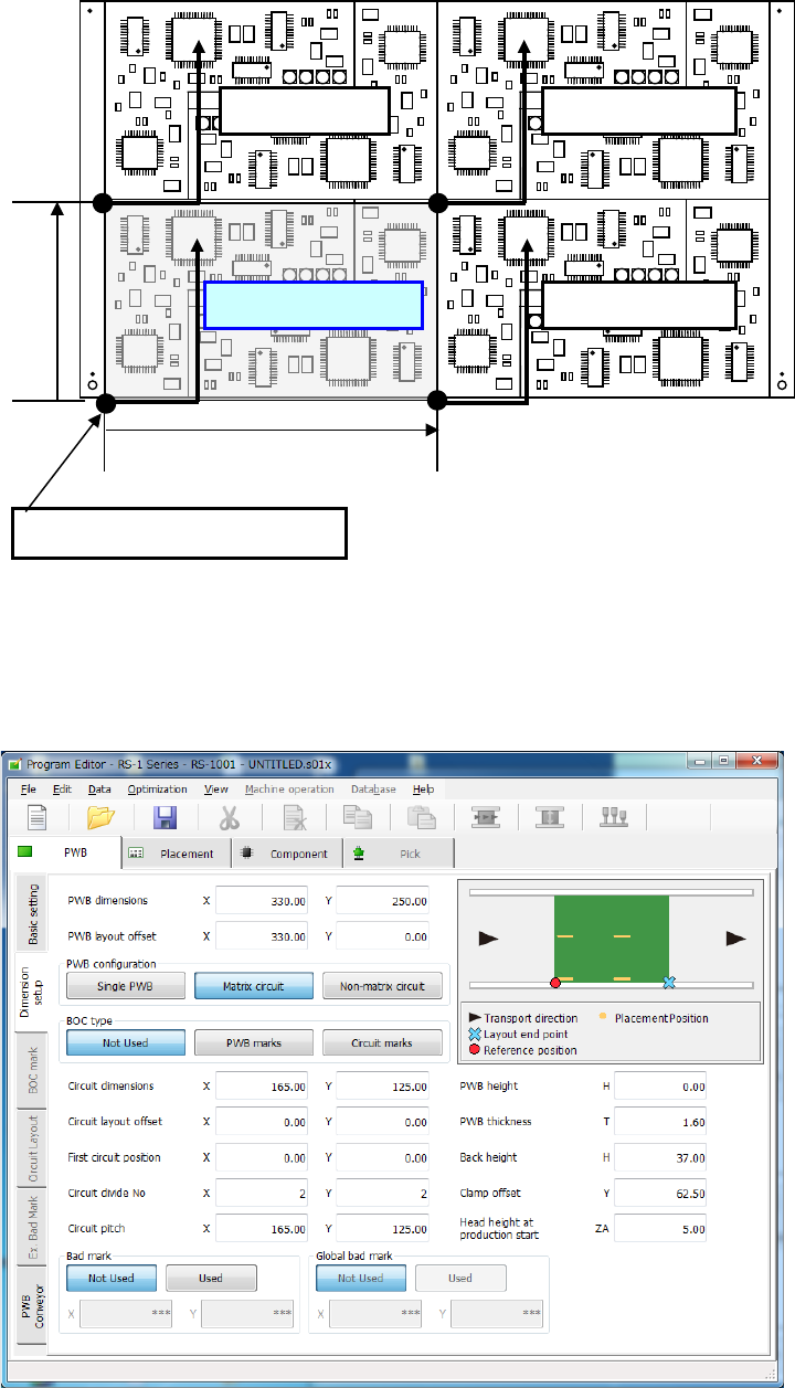
5) Circuit dimension
Enter the outer dimensions of the circuit (dimensions containing all of placement
coordinates and circuit marks).
Example
6) Circuit layout offset
Enter the distance from the circuit origin of the reference circuit to the left bottom corner (this
is an always fixed point regardless of the PWB transport direction) of the reference circuit.
7) First circuit position
Specify the reference circuit. Enter the position of the origin of the reference circuit viewed
from the PWB origin.
In the case of multi-circuit matrix, you can set the board reference position and the circuit
origin separately.
Specify the board reference position with the menu item “PWB layout offset,” and the circuit
origin with the menu item “First circuit position.”
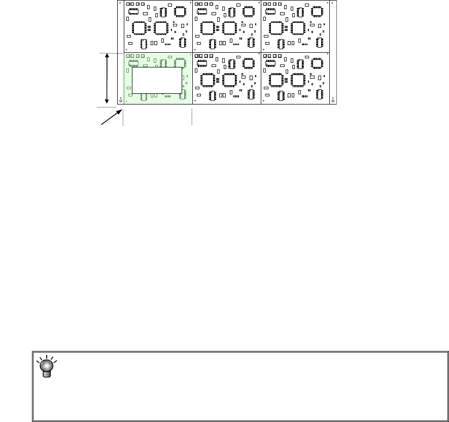
8) Circuit divide No
Enter the numbers of circuits in the X direction (or the PWB transport direction) and in the Y
direction (or the vertical to the PWB transport direction).
The maximum number of circuits varies depending on the setting of the menu item “Specify
Extended Bad Mark Coordinates” on the “Basic setting” screen.
The maximum number of circuits the system can create on a multi-plane matrix
PWB is shown below.
When a standard bad mark: 1200 circuits
When an extended bad mark: 1200 circuits
Circuit
dimensions, Y
Circuit
dimensions, X
Circuit layout offset
Reference
circuit
Part 1 Basic Operation Chapter 4 Creating a Production Program
4-18
9) Circuit pitch
Enter the distance between the circuits (the distance between the origins of two circuits, and
you have to enter a sign, + or – (minus).) in the X direction (or the PWB transport direction)
and in the Y direction (or the vertical direction to the PWB transport direction).
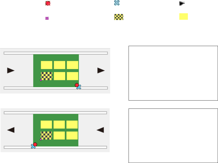
Example: data entry for a multi-plane matrix board
The circuit at the lower left corner is the reference circuit, and the lower left corner of the
circuit is the circuit origin in this example.
① For transport direction of L -> R
② For transport direction of R -> L
10) PWB height
11) PWB thickness
12) Back height
13) Clamp offset
Enter these menu items in the same manner as those for a single- circuit PWB.
PWB dimensions X=200 Y=120
PWB layout offset X=5 Y=-5
Circuit dimensions X=50 Y=30
Circuit layout offset X=0 Y=0
First circuit position X=-170 Y=15
Circuit divide No X=3 Y=2
Circuit pitch X=60 Y=50
PWB dimensions X=200 Y=120
PWB layout offset X=-5 Y=-5
Circuit dimensions X=50 Y=30
Circuit layout offset X=0 Y=0
First circuit position X=-20 Y=15
Circuit divide No X=3 Y=2
Circuit pitch X=60 Y=50
:Board reference position :Layout end point :Transport
direction
:First circuit position :Reference circuit :Circuit
*Neither the first circuit position nor each circuit is displayed on the screen actually.