RS-1_instruction manual.pdf - 第539页
Part 1 B asic O peration Chapter 4 Cr eating a Produc tion Progra m 4- 204 position is sh i fted fr om the regulate d position. See the descr i ption of the pick pos ition check in “ (6) Inspecti on 1 ” of Section 4. 3.5…
Part 1 Basic Operation Chapter 4 Creating a Production Program
4-203
“Component” data “List” screen.
• Notification: The system displays the “Question” message that asks you whether to
delete the corresponding component data.
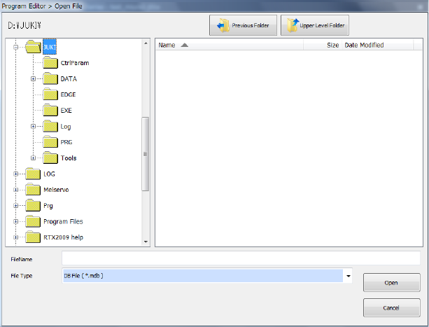
(3) Database file
Select a type of a database file you are to use. Note that you cannot select a database that
cannot be used.
A database is a file in which component data is registered. (For more details, see Chapter 5
"Database.")
You can use only one database with the Editor.
You can create two or more databases and operate them, but You have to specify the database
file to use according to the program.
・When you use the component database of the mounter main unit
<How to set>
① Select the <Machine Component DB> button.
② Press the <Browse> button, and select a database file on the “Open File” dialog box.
(4) Default Nozzle Selection
Specify a nozzle to be used by pressing either of the buttons, <Use 7500 nozzle as default> or
<Use 7502 and 7503 nozzle as default>. This selection changes the nozzle number the system
automatically selects on the “Component” data screen.
Example: When you select the button <Use 7500 nozzle as default>
When you enter “2 mm × 1.2 mm” as the component dimensions on the “Component”
data screen, the system automatically selects a “No. 7500 nozzle.”
(5) Fix nozzle selection even when component size is changed
Select whether to reset the default nozzle number when you change the component dimensions.
- Restore Defaults : Sets the default nozzle number.
- Fix : Does not reset the nozzle number.
(6) Default setting of the board thickness
Select whether to set the default value in the “PWB thickness” field displayed on the “PWB” data
screen when a new production program is created.
- Blank : Does not set the default value in the “PWB thickness” field.
- Fix : Sets the default value in the “PWB thickness” field.
(7) Pick Position Check
When you are to check the component pick-up position, enter the value for judging if a pick-up
Part 1 Basic Operation Chapter 4 Creating a Production Program
4-204
position is shifted from the regulated position.
See the description of the pick position check in “(6) Inspection 1” of Section 4.3.5.2 “Creating of
component data” of this chapter for a value to be entered in the “Threshold” field and the value
used for judging.
4.5.6 Machine operation
This command actually operates the main unit to take various actions.
The Machine operation menu provides menu items corresponding to each action.
The table below describes the sub menu corresponding to each menu item and outlines its
function.
Submenu item Overview
BOC mark
Checks a BOC mark recognition operation and saves the measured values.
Area mark
Checks an area mark recognition operation and saves the measured values.
Feeder bank (Front)
Checks a bank mark recognition operation and saves the measured values.
Feeder bank (Rear)
Place
Checks each coordinate position of the Placement data.
Pick position
Checks each coordinate position of the Pick data.
Pick height
Checks each height of the Pick data.
4.5.6.1 BOC mark
This is the function for checking your editing of a production program.
This function memorizes the measured coordinates where the system recognized a BOC mark,
and uses them to correct the coordinates when the system teaches the Placement data.
When you select the [Machine operation] command from the menu, and then the [BOC mark]
command, the dialog box for setting the measurement conditions appears on the screen.
CAUTION
To avoid a risk of injury, do not put your hands inside the machine
nor move your face or head close the machine while you are
operating the machine.
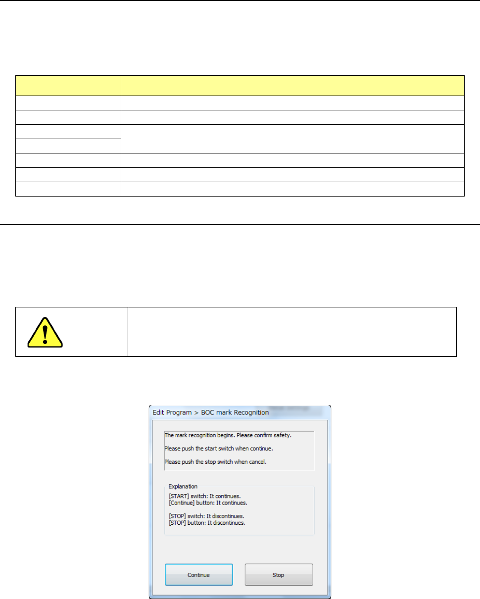
(1) Recognizing a BOC mark
If you select the [BOC mark] command when the cover opens, the confirmation screen
appears. After checking the safety, press the <START> switch or the <Continue> button.
Part 1 Basic Operation Chapter 4 Creating a Production Program
4-205
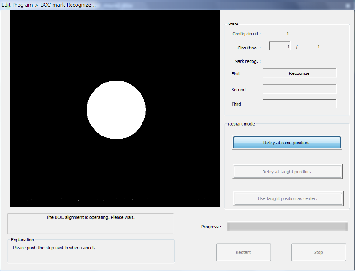
The following dialog box appears on the screen during BOC alignment operation.
The image shot with the OCC appears at the upper left corner of the screen.
To abort the operation for some reason, press the <Stop> button.
After the system stops recognizing a BOC mark, the start screen reappears.
1) State
The system display its operation status here.
• Circuit no
The number of circuit being recognized is displayed here.
(Normally, only a BOC of the reference circuit is recognized.)
• Mark recog.
The system displays the operation condition at the mark point being recognized now.
2) Restart mode
If the system fails to recognize a BOC mark during alignment of a BOC mark, you can select
each button of the “Restart mode” items.
3) Progress
The progress bar displays the ratio of the marks recognized already to the total number of
marks.