RS-1_instruction manual.pdf - 第351页
Part 1 B asic O peration Chapter 4 Cr eating a Produc tion Progra m 4- 16 (3) Mu lti - plane matrix PWB On a multi - p lane PWB, t wo or more circu its of the same type ar e arrange d. There are t wo types of m ulti - p …
Part 1 Basic Operation Chapter 4 Creating a Production Program
4-15
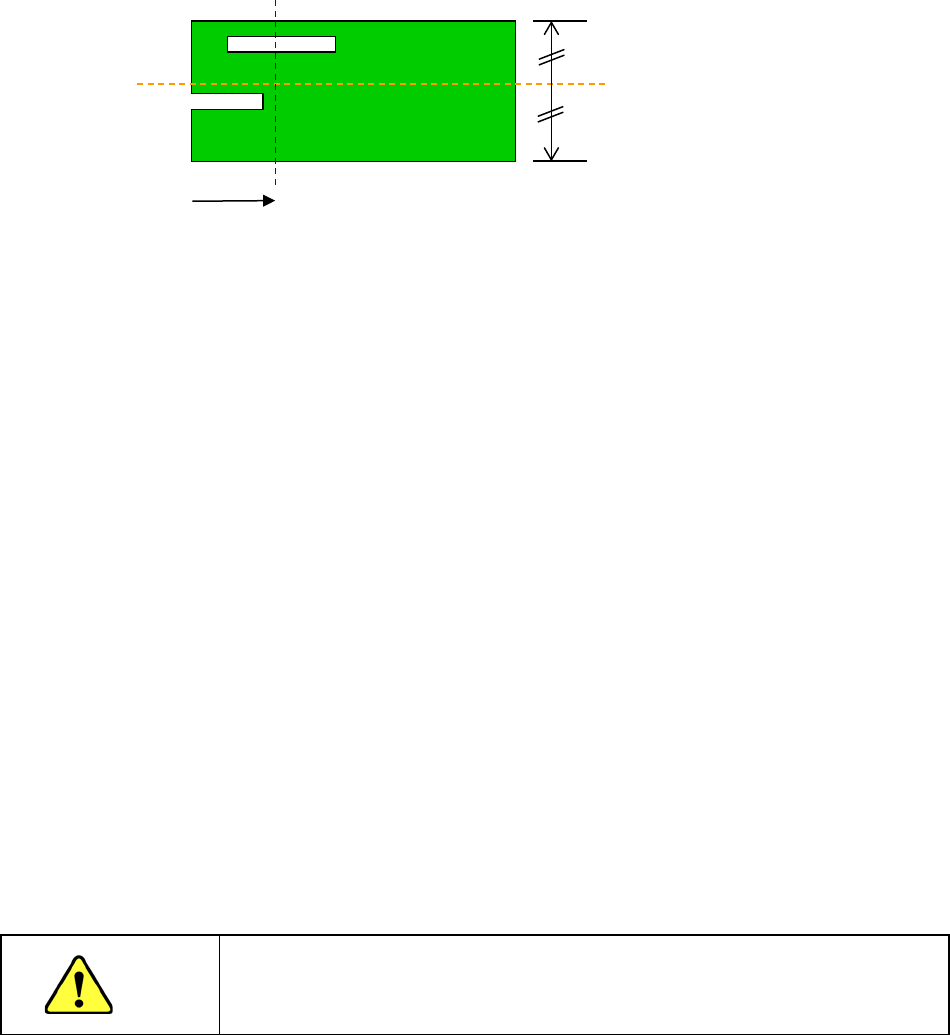
13) Clamp offset (Board whose X-dimension of the “PWB dimensions” exceeds the regulated
size (650 mm))
As the “Clamp Offset,” specify the detection position (Y-coordinate) of the sensor (HMS) that
it to detect a board when the board is fed twice.
* Notes to be applied when you specify the “Clamp Offset”
If the default position satisfies the following conditions, you have to change the
setting of the menu item “Clamp Offset.”
In the 50-mm area from the rear edge of a board
1. there is a “notch” or a “slit” of a board,
2. there is a tall component (3 mm or taller) or a lead of a component or
3. there is a mirrored section or a concave/convex section (for example, when a jig board is
used).
To change the setting, specify the position that does not satisfy the conditions above, is not
near any conveyor rail, and is located within the area whose height can be measured with
the sensor (board transport reference surface ± 10 mm).
(It is recommended to specify a position at which any component is not placed.)
After specifying the offset, check to see if a board can be fed and clamped twice (HMS
clamp) normally by selecting the [Pwb conveyor] command, and then the <Pwb load (2nd)>
button.
14) Head height at production start
Set a height necessary to determine the specifications of the ZA-axis height at production
start. When components are placed on the PWB in the upstream process or when the boss
is protruded from the PWB while components are placed on the back side, set this height.
Additionally, when a tray holder or custom-order unit is always installed in the machine, set
the maximum height among them.
The initial value is blank and the data is not completed with blank. Therefore, it is necessary
to enter the head height at production start when the production program of other model
(without the head height at production start) is loaded.
CAUTION
If the head height at production start is set to a low level, this may cause a
machine crush or component failure. Be sure to enter a correct value after
checking the upstream process of the line or the machine status.
15) Global bad mark
You cannot use this menu item for a single-circuit PWB.
16) Bad mark
You cannot use this menu item for a single-circuit PWB.
Default position (Sensor
detecting line)
Slit
Notch
50mm
Part 1 Basic Operation Chapter 4 Creating a Production Program
4-16
(3) Multi-plane matrix PWB
On a multi-plane PWB, two or more circuits of the same type are arranged.
There are two types of multi-plane PWBs: matrix circuit PWB and non-matrix circuit PWB.
The angles of all circuits are equal to one another, and the distance between two consecutive
circuits (pitch) is equal on a matrix circuit PWB. As Placement data, create data on one circuit
(called as “reference circuit”), as PWB data, enter information on the circuit arrangement (such as
the pitch between circuits and the number of circuits).
Pitch Y
Reference circuit
Fourth circuit
Second circuit
Third circuit
Pitch X
Origin of the reference circuit
Part 1 Basic Operation Chapter 4 Creating a Production Program
4-17
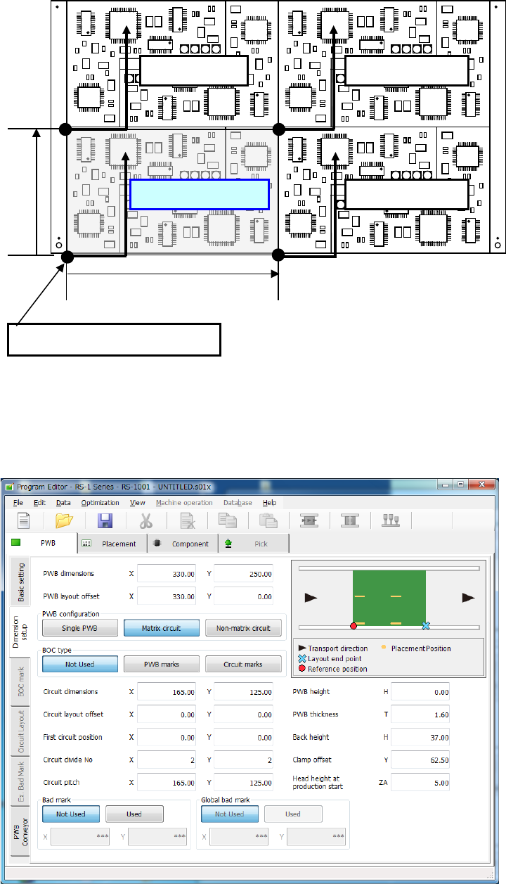
1) PWB dimensions
Enter the dimensions of the PWB including all circuits.
2) PWB layout offset
Enter the length from the PWB position reference to the PWB layout end point in the same way
as a single-circuit PWB.
3) PWB configuration
Select the radio button “Matrix circuit.”
When dimension settings are performed for the multi-circuit matrix and then this matrix is
changed into the multi-circuit non-matrix, expansion to the non-matrix circuit layout is
automatically performed.
4) BOC type
◆ Not Used: Select this button when any BOC mark is not used.
◆ PWB marks: Select this button to use BOC marks on a board to correct the
component placement coordinates.
◆ Circuit marks: Select this button to recognize BOC marks of each circuit on a
multi-plane (circuit) board to correct component placement coordinates.
If there are many circuits on a board, this selection requires much time
to recognize marks, but the accuracy of component placement tends to
be higher than that when you select the <PWB marks> button.
5) Circuit dimension
Enter the outer dimensions of the circuit (dimensions containing all of placement
coordinates and circuit marks).
Example
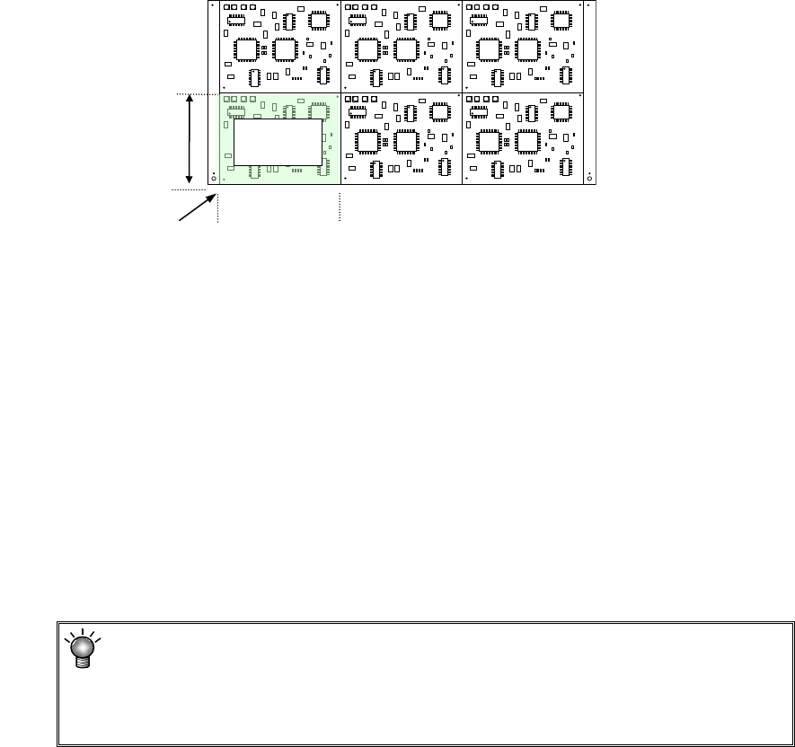
6) Circuit layout offset
Enter the distance from the circuit origin of the reference circuit to the left bottom corner (this
is an always fixed point regardless of the PWB transport direction) of the reference circuit.
7) First circuit position
Specify the reference circuit. Enter the position of the origin of the reference circuit viewed
from the PWB origin.
In the case of multi-circuit matrix, you can set the board reference position and the circuit
origin separately.
Specify the board reference position with the menu item “PWB layout offset,” and the circuit
origin with the menu item “First circuit position.”
8) Circuit divide No
Enter the numbers of circuits in the X direction (or the PWB transport direction) and in the Y
direction (or the vertical to the PWB transport direction).
The maximum number of circuits varies depending on the setting of the menu item “Specify
Extended Bad Mark Coordinates” on the “Basic setting” screen.
The maximum number of circuits the system can create on a multi-plane matrix
PWB is shown below.
When a standard bad mark: 1200 circuits
When an extended bad mark: 1200 circuits
Circuit
dimensions, Y
Circuit
dimensions, X
Circuit layout offset
Reference
circuit