RS-1_instruction manual.pdf - 第535页
Part 1 B asic O peration Chapter 4 Cr eating a Produc tion Progra m 4- 200 4) T eachin g the detect i on fra me When you fin ish the oper ation (3), the system autom atically displays t he windo w whose size is 1.5 times…
Part 1 Basic Operation Chapter 4 Creating a Production Program
4-199
2) Selecting a template type
Next, select “PR” to judge a mark.
[ ]
[ ]
[ ]
[ ]
[ ]
[ ]
[ ]
[ ]
[ ]
[ ]
[ ]
[ ]
[ ]
[ *]PR
**********
The size of a template is 256 × 256 pixels (approximately a quarter of the screen). If you
specify a too large template, the system displays an error and returns to the procedure for
setting the scale frame.
3) Teaching the center of the template
Press the screen in the up/down direction to
align the * mark with the “PR” position, and
then press the <OK> button.
The message “Select Mark by Up or Down
key” appears on the bottom of the screen.
**********
The scale frame and the crosshair cursor appear on the screen.
Move the crosshair cursor to align it with the center of the template
(th
is position matches the coordinates of a mark specified on the
“PWB” data screen). Press the <OK> button to decide the
center.
The message “TempMatch
– Set Center” appears on the bottom
of the screen.

Part 1 Basic Operation Chapter 4 Creating a Production Program
4-200
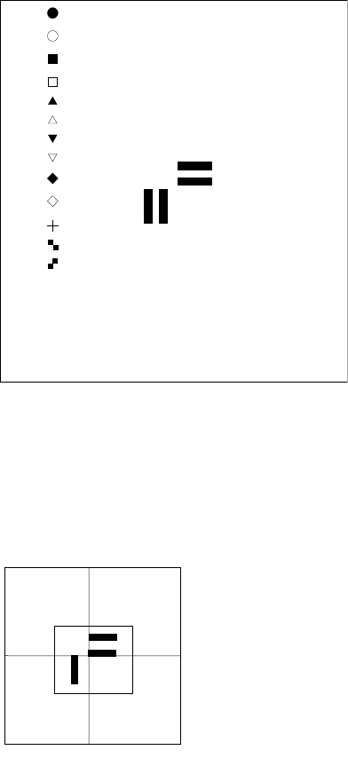
4) Teaching the detection frame
When you finish the operation (3), the system automatically displays the window whose size
is 1.5 times that of the frame you set at (1) so that it can be aligned with the center of the
screen (default window).
To change the detection frame, follow the procedure described at (1).
If you do not change the detection frame, press the <OK> button.
When you press the <Prev> button at this point, the system returns to the procedure for teaching
operation of the scale frame.
5) End of teaching
When the system finishes teaching operation for recognizing the template, it displays (*)
next to the mark on the "Program Editor" screen indicate that it finished teaching operation.
Perform the teaching operation for recognizing a mark for all marks to be used.
If you press the <CANCEL> button during teaching, the system finishes teaching at that
point (in this case, the data that has been entered until that point will become invalid).
Even though you press the <CANCEL> button, any device will not move.
• Notes on setting of a template
i) Check to see if there is no pattern similar with the template you set inside the detection
frame.
ii) Set the size of the pattern to 0.5 mm to 3 mm in the same manner as a standard mark.
iii) Specify the designed values (CAD data) as coordinates. The system cannot obtain the
center position correctly when it teaches the user-designated template. Since the system
teaches the pattern by moving the crosshair cursor, the position you specified is regarded
as the center position as it is (Since the system calculates and sets the center position for
the standard mark pattern, any error is not generated).
iv) You cannot execute the [Vision Copy] command for any user-designated template.
Set the detection frame.
Follow the procedure for setting the scale frame.
A
dotted
line indicates the frame for setting a template, but it
is no
t displayed on the screen actually.
The message “Set Left
-Top Point” is displayed on the
bottom of the screen.
When you finish adjusting the frame, press the <OK> button.
The message “Set Right
-Bottom Point” is displayed on the
bottom of the screen.

Part 1 Basic Operation Chapter 4 Creating a Production Program
4-201
• Patterns registrable as a user-specified template
1) Patterns registrable as a user-specified template
① Wiring pattern
② Pad/land pattern that is not screen-printed (without solder paste)
③ PWB mark other than the JUKI standard (whole or a part)
2) What is required for registration as a user-specified template
The through-hole/pier hole pattern creating process is different from drilling process,
so that the same positional relation cannot be provided at all times. (The hole
position for the pattern is unstable.)
To register the template on the basis of the through-hole/pier hole, register this
template including peripheral wiring pattern instead of registration of itself.
3) What cannot be registered as a user-specified template
① Silk (character) printing pattern
The pattern/pad creating process is quite different from the silk printing process, so
that the placement position cannot be determined on the silk pattern.
② Screen-printed pad/land pattern
The screen-printed solder paste is granular. Accordingly, the luminous status
varies depending on the environment and conditions. Template matching is
resistant to changes of lighting conditions but cannot follow changes of polarity
(normal/reverse rotation).
③ A similar pattern exists on the recognition screen.
④ Template with a small difference between brightness and darkness
⑤ The pattern selection (size) or angle changes.
In particular, when a part of the pattern is registered as a user-specified template, the scale
change is incorporated into the recognition accuracy as it is. Register the whole pattern as
a user-specified template.
Regarding an angle change, its effect is increased (the recognizing position is shifted) as the
position of center of gravity (described before) of the template is separated from the center of
the template.
Set the user-specified template so that the center of gravity may be coincident with the center
of the template if possible.