RS-1_instruction manual.pdf - 第724页
Part 2 D etaile d Descript ion of E ach Functi on Chapter 8 Machine Set up 8- 16 (2 ) S etting i tem s No. Items Descripti on 1 A T C No A T C No. : 1 to 4 5 2 Nozzl e No Nozzle No . to be assigned t o A T C 3 Nozzl e Ty…

Part 2 Detailed Description of Each Function Chapter 8 Machine Setup
8-15
If USB memory has not yet been incorporated into the USB port or if the USB memory used is
defective and cannot be called up, by default, the additional nozzle data folder reference screen
appears.
The data file of existing additional nozzles is housed here.
Nozzle setup
When you select the [Nozzle setup] command, the following screen appears.
(1) Purpose of use
The setting item “Nozzle height” is to be used to make fine adjustments of the height for
measuring a component with laser.
The setting item “Vacuum” is to be used to judge if there is a nozzle or a component. Note
that the system uses laser to check to see if there is a nozzle or a component, and so values
set here are used as supplementary information only.
Part 2 Detailed Description of Each Function Chapter 8 Machine Setup
8-16
(2) Setting items
No.
Items
Description
1
ATC No
ATC No.: 1 to 45
2
Nozzle No
Nozzle No. to be assigned to ATC
3
Nozzle Type
Nozzle type to be assigned to ATC (automatic acquisition only)
4
Vacuum
Vacuum value with a nozzle (automatic acquisition only)
5
Nozzle height
Length offset for the reference nozzle (automatic acquisition only)
6 Reflection
OK: Low reflection nozzle, NG: High reflection nozzle or
measurement not executed
7 Load cell
OK: A load cell is checked normally., NG: An error is detected
with a load cell check or a load cell check has not been run yet.
(3) How to set a nozzle
The reference head on which a nozzle is mounted measures the height of the nozzle tip
(measured value is to be entered into the “Noz. height” field) and nozzle width (to be entered
into the “Noz. No.) with laser. In addition, the reference head obtains the vacuum value
also.
1) Nozzle No
Set the number of a nozzle to be assigned to the ATC number displayed on the left.
a) The “ATC No” is a number assigned to the ATC, and enter the number indicating a
nozzle to be assigned to this ATC number.
b) The nozzle number on which the focus is located can be set. Validate the entered
characters with the [ENTER] key or the [Field Movement] key. You can enter a
nozzle number within the range shown in the table below.
No. Setting item Range
1 Nozzle No 7100 to 8999 or no assignment (no entry)
Eliminate input numerals from cells with the [DEL] key or with the [BACK SPACE] key,
then validate with the [ENTER] key or the [Field Movement] key. The nozzle assignment
is canceled and everything displayed for the assigned ATC is eliminated.
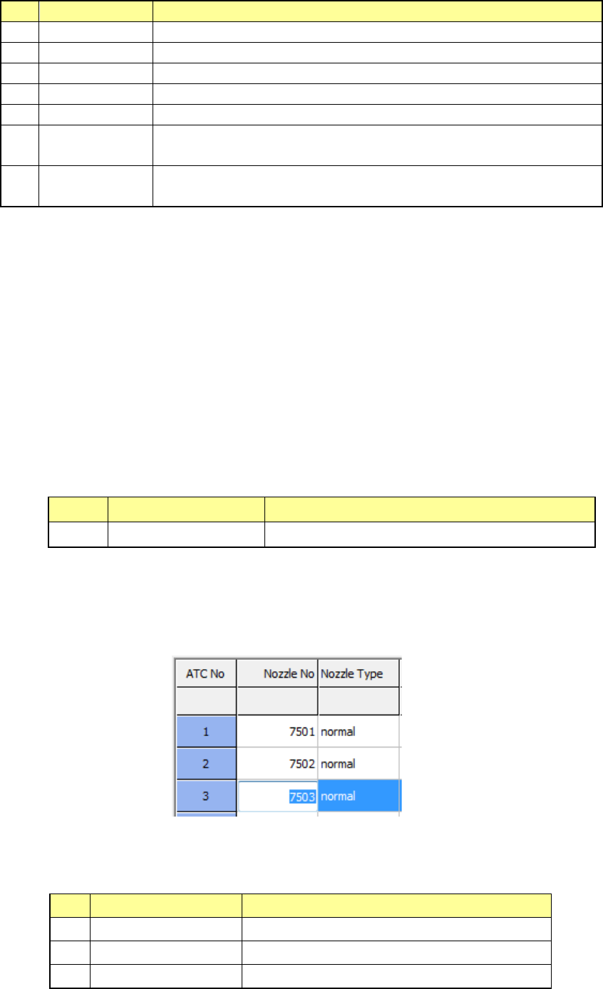
Example: In this case, a nozzle number is set in the “ATC” whose number is “3.”
2) Nozzle Type
The type of a nozzle to be attached to the ATC number displayed on the left of the
screen is displayed here.
No.
Setting item
Description
1
Normal
Normal nozzle
2 T-type Cleaner type nozzle
3
Gripper
Gripper nozzle
Part 2 Detailed Description of Each Function Chapter 8 Machine Setup
8-17
3) Vacuum
Set the vacuum value when a nozzle is mounted on the reference head (Head 3).
This value is used to judge whether a nozzle is mounted or whether a component is
located on the regulated position. Note that the value set here is just auxiliary
information since the system uses laser to check whether a nozzle is mounted or not or
whether a component is located at the regulated position.
4) Nozzle height
Set the offset value of the length with viewed from the reference nozzle.
This value is used to make fine adjustments for controlling the height when the system
measures a component with laser.
5) Single Assignment
When you press the <Single Assignment> button on the right side of the screen, the
system attaches a nozzle to the head of the ATC number in which the focus is located,
and sets each value.
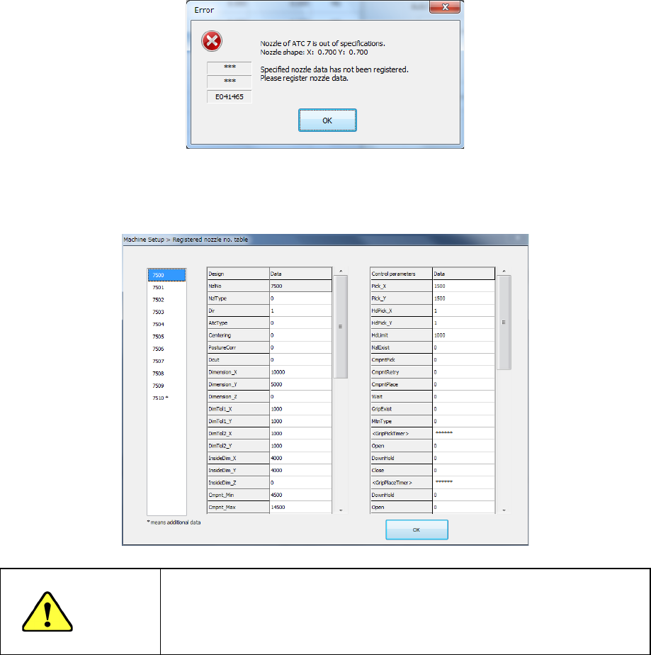
Note 1) If the obtained nozzle outer dimensions are not within the regulated range
and the system judges that there is no registered nozzle information on this specified
nozzle according to its width, the following message appears on the screen. In this
case, select another nozzle, and enter data on the nozzle manually.
Note 2) If the obtained nozzle outer dimensions are not within the regulated range
and the system judges that there is any registered nozzle information on the specified
nozzle according to its width, select a nozzle number from the list of nozzles.
If the desired nozzle is not in the list, select it and manually enter its data.
WARNING
When you select <OK>, the axis is moved and a nozzle can be mounted
or removed. Be sure to check whether any worker is in the equipment
before pressing <OK>. To avoid a risk of injury, do not put your hands
inside the machine nor move your face or head close the machine while
the machine is operating