RS-1_instruction manual.pdf - 第431页
Part 1 B asic O peration Chapter 4 Cr eating a Produc tion Progra m 4- 96 The “Vi sion 2” tab allows you t o set informat ion on leads located on eac h of the left and right sides . Menu item Overvie w Length Enter the l…
Part 1 Basic Operation Chapter 4 Creating a Production Program
4-95
The “Vision 2” tab allows you to set information on leads located on each of the top and bottom
sides.
Menu item
Overview
Length
Enter the length of a section of a lead that is in contact with a board.
Width
Enter the width of a lead.
Count
Enter the number of leads when a component type is a lead component.
Start 1 to 3
Enter the position of a missing lead.
The input range is from 0 to the number of leads (default: 0).
Miss 1 to 3
Enter the number of missing leads.
The input range is from 0 to the number of leads (default: 0).
6) TSOP
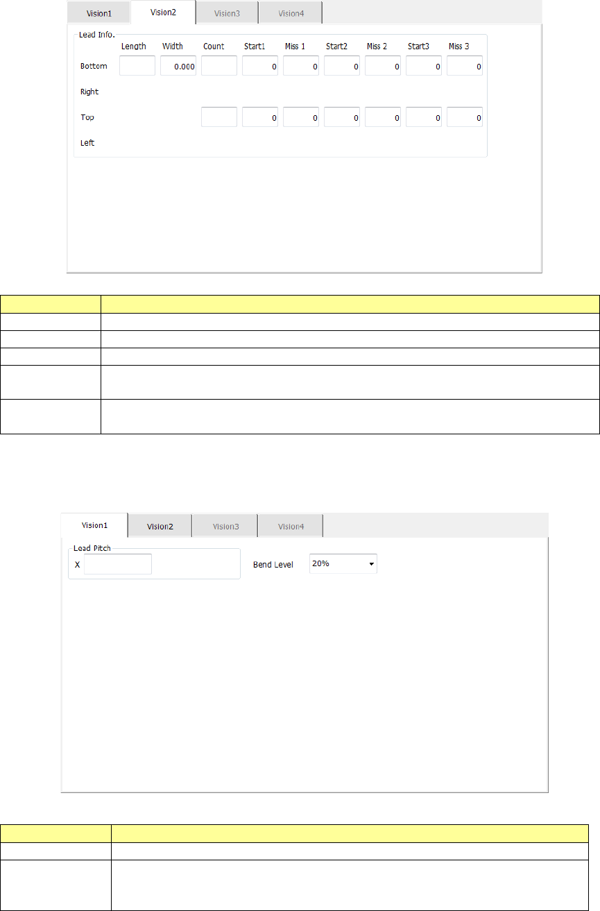
The “Vision 1” tab allows you to set the lead pitch and the lead bending level.
Menu item
Overview
Lead Pitch
Enter the distance between two consecutive leads.
Bend level
Select the bending level of a lead to be detected among “15 %,” “20 %,”
“25 %,” “30 %” and “None.”
The default value is 20 %.
Part 1 Basic Operation Chapter 4 Creating a Production Program
4-96
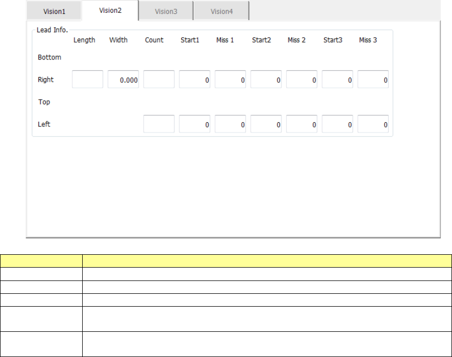
The “Vision 2” tab allows you to set information on leads located on each of the left and right sides.
Menu item
Overview
Length
Enter the length of a section of a lead that is in contact with a board.
Width
Enter the width of a lead.
Count
Enter the number of leads when a component type is a lead component.
Start 1 to 3
Enter the position of a missing lead.
The input range is from 0 to the number of leads (default: 0).
Miss 1 to 3
Enter the number of missing leads.
The input range is from 0 to the number of leads (default: 0).
Part 1 Basic Operation Chapter 4 Creating a Production Program
4-97
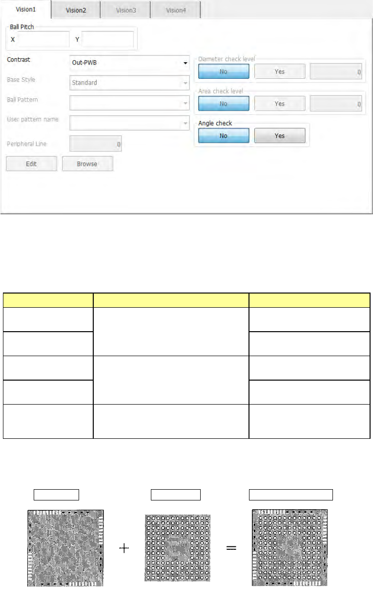
7) BGA, FBGA
The “Vision 1” tab allows you to set the ball pitch, the contrast (recognition type), the base
style, the ball pattern and each check.
① Ball Pitch
Enter the distance between two consecutive balls.
② Contrast (recognition type)
Set the recognition type.
Choice Recognition range Type
Out – PWB
Only balls on the outer periphery of
a component are recognized.
(This cannot be selected for an
FBGA component.)
Board type whose mold
section looks black
Out–Ceramic
Ceramic type whose mold
section looks white
All balls–PWB
All balls of a component are
recognized.
Board type whose mold
section looks black.
All balls–Ceramic
Ceramic type whose mold
section looks white
All land
All lands of a component are
recognized. (This choice is for an
LGA component.)
Board type whose mold
section looks black
When you select "All balls," the recognition pattern can be set by setting "Base style"
and "Ball pattern."
Base Style + Ball Pattern → Recognition pattern