RS-1_instruction manual.pdf - 第639页
Pa r t 2 D et ai l ed Des c r i pt i o n of Ea c h F unc t i o n Chapte r 6 G e neral - Purpose Vision Co mpone nt 6-8 Par am et er 1 and Par am et er 2 You ca n set a n of f set am ount in th e le ad l eng th di recti…
Part 2 Detailed Description of Each Function Chapter 6 General-Purpose Vision Component
6-7
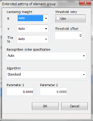
7) Settings on the “Extended setting of element group” screen
Make extended data settings of each element.
Centering Weight
Set weighting of each direction: X, Y and theta.
“Weight” means weighting of an element group for positioning a component. If you set a
smaller value in this field for an element group of a component whose accuracy is low, the
component can be positioned stably.
Set a value from 1 to 100.
Threshold retry
Turn on/off the retry operation activated with a threshold value. For example, if you turn it
on when the contrast is unsatisfactory, a recognition error may be fixed.
Threshold offset
In the same manner as contrast correction for recognizing the outline of a component, you
can set a threshold offset. If a component cannot be recognized stably with a threshold
value automatically calculated, set a threshold offset here.
Recognition order specification
If a component is recognized stably when you specify recognition order, set the recognition
order here. Normally, do not change the setting “Auto.”
Auto: does not specify the recognition order.
Definition order: recognizes components in the defined order.
Algorithm
Set the algorithm for a side, a corner and a lead. For a component whose outline is to be
recognized, coarse positioning of a component is added to the standard algorithm to
improve the response capability for a positioning error and an irregularly-shaped component.
You can select the conventional algorithm also.
Other elements are parameters for expansion in the future.
◇ Standard: uses the standard algorithm.
◇ Conventional algorithm: uses the conventional algorithm.
For other elements, you can select an algorithm to perform the recognition when a part of
the lead component is hidden by sheet metal or the shape base matching (3rd) is used in
addition to the standard algorithm.
◇ Standard: uses the standard algorithm.
◇ Algorithm 1: Performs the recognition with the DOG filter in addition to the coarse
positioning with other elements.
◇ Algorithm 2: Performs the positioning recognition with the DOG filter in addition to the
coarse positioning with the shape base matching (3rd).
Part 2 Detailed Description of Each Function Chapter 6 General-Purpose Vision Component
6-8
Parameter 1 and Parameter 2
You can set an offset amount in the lead length direction of the detection window using
parameter 1 when performing the DOG filter recognition. (The unit is μm.)
The parameter 2 is a parameter for expansion in the future, and not be used now.
8) Missing Elements
If an element group has a missing element, specify the missing element information from a
missing element located nearest the first element sequentially. You can specify up to four
missing elements per column or row.
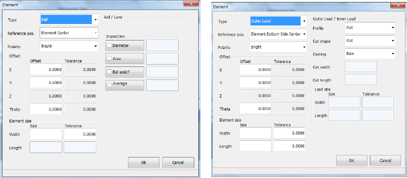
9) Element
Enter the information on an element.
• Type
Select an element type.
The contents of the displayed list vary depending on your entry at 5) (the right screen
appears when you select the “1D” radio button).
- Outer Lead : Gull-wing type lead (such as a QFP)
- Inner Lead : J-lead (such as a QFJ)
- Column : a ball or land whose height can be recognized enough.
- Mark : a component that does not require any inspection because it is not an
electrode such as a mark.
- Side : a component whose element is irregular-shaped, so the system can
recognize its side only.
- Corner : a component whose element is irregular-shaped, so the system can
recognize its corner only.
See the next page for how to specify the “Type.”
• Reference pos. (position)
Specify the first element reference position.
We recommend that you specify the “center of the bottom side (center of the lead tip)”
for a lead component, or “the center of an element (center of a ball)” for a ball
component.
• Polarity
Specify the brightness of an element.
If an element looks brighter than its background, select “Bright.”
• Offset
Specify this field if the “first element position” of an element group should be shifted
further than that already specified.
• Element size
Enter the length and width of an element.
Part 2 Detailed Description of Each Function Chapter 6 General-Purpose Vision Component
6-9
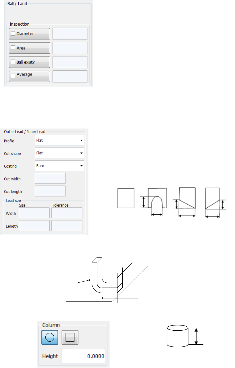
• Ball/Land
When you select “Ball” or “Land” in the “Type” field, these fields appear on the screen.
Select the shape of a ball or land. (However, the system does not distinguish the shape
currently.)
Specify whether to check the shape or not, and enter the judging
level.
− Diameter:
Specify whether to check the diameter. When checked, the
system checks each ball based on the average diameter of all
checked balls.
− Area: Specify whether to check the area.
− Ball exist?:
Specify whether to check that there is a ball or not. The initial
value “30 %” indicates that the system can detect the
condition: 20 % of a ball is cut away.
− Average diameter:
Specify whether to check the diameter with comparing the
average diameter of checked balls and the input diameter
• Outer Lead/Inner Lead
When you select “Outer Lead” or “Inner Lead” in the “Type” field, these fields appear on the
screen.
− Profile: Specify the lead type.
− Cut shape:
Specify the shape of the cut section if the tip of a lead is cut:
− Cut width, Cut length:
When you select “U-shape cut,” “Left bottom cut” or “Right
bottom cut,” enter these fields.
− Coating:
Specify the coating type of a lead. Not used at the present.
− Lead size:
For a gull-wing lead, enter the width and length of the tip of a lead that is in contact with a
board.
• Column
This screen appears when you select “Column” in the “Type” field. Not used currently.
高さ
Height
Flat
Length
U-shape
cut
Width
Left bottom
cut
Right bottom
cut
Width
Width
Length
Length
Width
Lead
Board