RS-1_instruction manual.pdf - 第29页
Part 1 B asic O peration Chapter 1 Overv iew of the Machine 1- 11 Configuration of the compone nt feeder T otally two compone nt feeder banks are prov i ded: one bank is located at the front and rear of the PWB transp or…
Part 1 Basic Operation Chapter 1 Overview of the Machine
1-10
Configuration of the machine
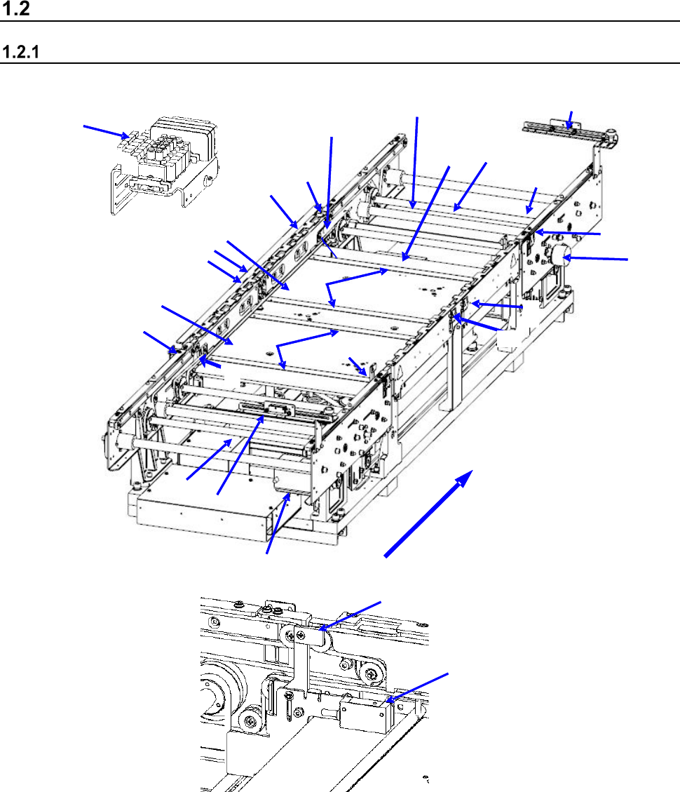
Configuration of the board transfer section
・ Configuration of the board transfer section (for a single-lane conveyor)
2
1
15
11
3
4
8
10
11
12
10
13
14
17
16
18
11
7
5
9
12
6
21
20
22
23
Board transfer direction
1 IN sensor
9 Board transport electromagnetic
valve
17 Support pin detection sensor light receiving
section
2 OUTsensor
10 Conveyor motor
18 Stopper sensor
3 WAIT sensor fiber light receiving section
11 Drive shaft
19 Stopper
4 WAIT sensor fiber light emitting section
12 Side beam
20 (WAIT2 sensor fiber light receiving section)
5 C-OUT sensor fiber light receiving section
13 Support table IN
21 (WAIT2 sensor fiber light emitting section)
6 C-OUT sensor fiber light emitting section
14 Support table OUT
22 (WAIT2 sensor fiber light receiving section)
7 PWB guide
15 Automatic width adjustment motor
23 (WAIT2 sensor fiber light emitting section)
8 Support table origin sensor
16 Support pin detection sensor light
emitting section
18
19
Part 1 Basic Operation Chapter 1 Overview of the Machine
1-11
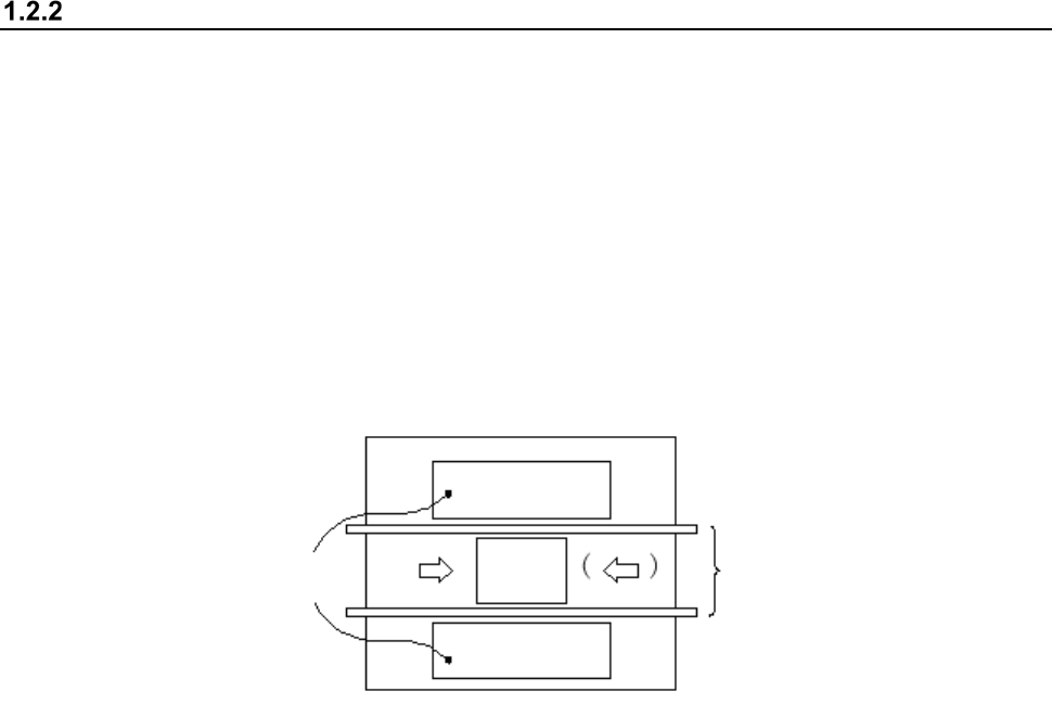
Configuration of the component feeder
Totally two component feeder banks are provided: one bank is located at the front and rear of the
PWB transport unit respectively. The component supply method varies depending on the package
style of components: tape, or tray.
Components fed by a tape (chip components) or those fed in a stick are mounted on the feeder
bank with using a tape feeder, then carried in the main unit.
A tray component is supplied by a tray holder, a matrix tray changer or a matrix tray server.
A tray holder or matrix tray server, can be mounted on the rear of the machine.
Using the Feeder exchange trolley (option), you can attach and detach the feeder bank from the
mounter and make an external setup.
Feeder banks
PWB
Rear
Front
PWB transport unit
* Left to right transport (IN and OUT are inverted for right to left transport)
Part 1 Basic Operation Chapter 1 Overview of the Machine
1-12
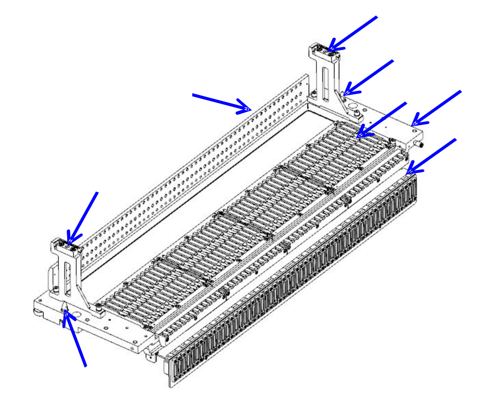
Part names of the bank for the electric tape feeder
Insert the electric tape feeder along the rail guide ① until it is in contact with the fixing block ②
and make the positioning.
Set the electric tape feeder on the bank, seeing the position label ③.
The bank mark ④ is intended to correct the position and posture of the bank.
①
Rail guide ③ Position label ⑤ Locate pin
②
Fixing block ④ Bank mark ⑥ Bank base
④
①
③
⑤
⑥
②
⑤
④