RS-1_instruction manual.pdf - 第607页
Part 1 B asic O peration Chapter 4 Cr eating a Produc tion Progra m 4- 272 b) For lead/land sett ing A component part is auto matically detecte d and the inclination is corr ected. At this time, set the detect ing metho …
Part 1 Basic Operation Chapter 4 Creating a Production Program
4-271
Detecting method
Explanation
1 side
The inclination of a component side is automatically detected and
corrected.
1 lead column
The inclination of a lead column is automatically detected and corrected.
2 lead columns
The mid-point of 2 lead columns is automatically detected and the
inclination is corrected so that the straight line connecting 2 points may be
parallel.
2 leads
The end coordinates of 2 leads are automatically detected and the
inclination is corrected so that the straight line connecting 2 points may be
parallel.
2 corners
Two corners are automatically detected and the inclination is corrected so
that the straight line connecting 2 corners may be parallel.
Optional 2 points
The inclination is corrected so that the optional 2 points specified by user
may be parallel.
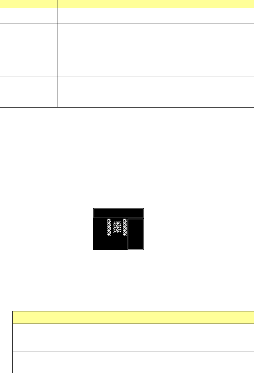
d) Division vision photographing (for division recognition)
At division recognition, the divided visions are photographed after the component inclination
is corrected. After that, the photographed visions are composed into a single vision, and
then this vision is displayed in a superimposed form.
④ Exclusion area setting (BGA component)
In case there is bright portion other than electrodes, specify an exclusion area. To specify
this exclusion area, press the <Add> button.
The window frame corresponding to the component outline is displayed on the VCS monitor.
Then, specify the exclusion area (bright portion other than electrodes). Press the <End
Teaching> button to finish the exclusion area specification. The number of exclusion areas
may be zero.
⑤ Component center teaching (general-purpose vision component)
a) For pole/land setting
Specify the center of the component by shifting the cursor. Specify the center of a
component by vision recognition or manually.
The specifying method for the center of a component depends on a combination of
component center setting (vision recognition or manual) and cursor type (cross or window).
Image recognition Manual
Cross
Specify the upper left and upper right poles of a
component and obtain the center of each pole.
Specify the mid-point between center positions of
these poles as the center of the component.
Specify the center of a
component directly.
Window Obtain the center of a component from the pole
layout provided in the set window frame.
Specify the center of the set
window frame as the center of
the component.
Part 1 Basic Operation Chapter 4 Creating a Production Program
4-272
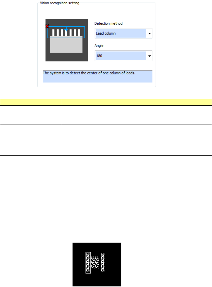
b) For lead/land setting
A component part is automatically detected and the inclination is corrected. At this time,
set the detecting method and the detecting angle.
Detecting method
Explanation
Center of circumscription
The component is scanned from the outside and the center of
circumscription of the bright portion is automatically detected.
Center of lead column
The center of lead column is automatically detected.
Center of 2 lead columns
Each mid-point of 2 lead columns is automatically detected and the
center of the 2 mid-points is specified as the center of the component.
2 corners
Two corners are automatically detected and the mid-point of the 2
corners is specified as the center of the component.
Optional 1 point
The user specifies the center of the component directly.
Optional 2 points
The center of the optional 2 points specified by user is specified as the
center of the component.
⑥ Pole area setting (general-purpose vision component (pole/land)
The window cursor corresponding to the outline of the component is displayed.
Perform teaching for the window so that the only the electrode of the same diameter may be
included in the window.
When you press the <Add> button, the window cursor corresponding to the outline of the
component is displayed. Then, set the area.
When you press the <End Teaching> button, the addition of area is finished.
It is necessary to set at least one pole area.
Part 1 Basic Operation Chapter 4 Creating a Production Program
4-273
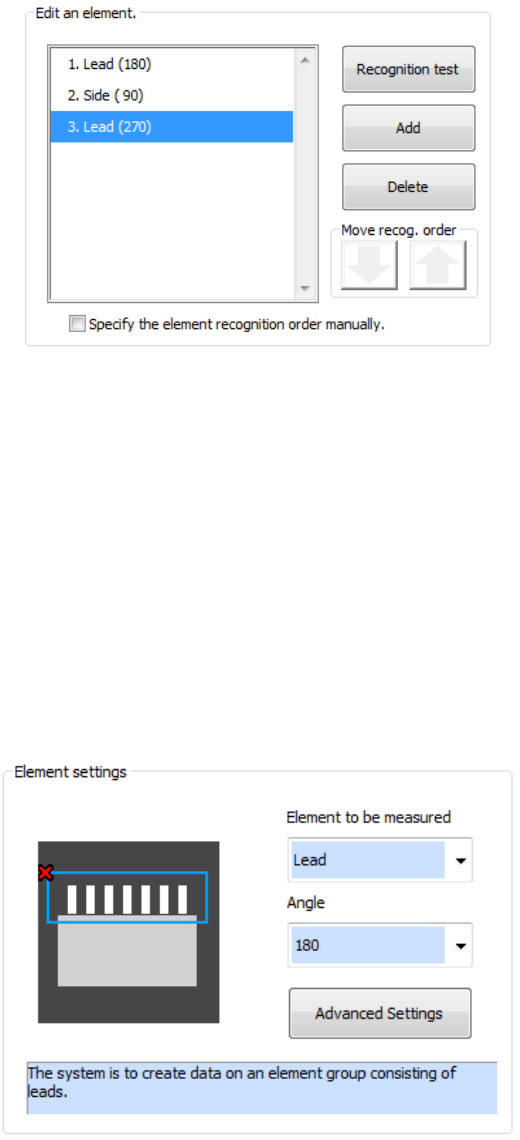
⑦ Element editing (general-purpose vision component (lead/outline))
Addition, deletion, and recognition order for multiple element groups are performed. In
addition, a recognition test can also be made.
In the initial status of element editing, the element setting screen appears automatically.
a) To add a new element group, press the <Add> button.
Set the type and angle of the element to be added and then add the element group. When
you press the detailed setting button, a detailed setting dialog is displayed to perform
settings more finely.
b) To delete an existing element group, select the element group to be deleted and press the
<Delete> button.
c) To test whether an element can be recognized according to the settings of the current
element group, press the <Recognition test> button.
d) To change the element group recognition order, check off "Specify the element recognition
order manually."
e) To change the recognition order, select the element group to be changed and press the
Up/Down button of "Recognition order shift." The element group position is shifted up and
down.
f) After completing editing all the element groups, press the <End Teaching> button.