RS-1_instruction manual.pdf - 第1017页
Part 2 D etaile d Descript ion of E ach Functi on Chapter 12 Handling th e Optional Device s 12 - 133 12.18 R- ATC Plate An R - ATC unit is attached on an RS - 1R instead of a n A TC unit . The R - ATC u nit has the st r…
Part 2 Detailed Description of Each Function Chapter 12 Handling the Optional Devices
12-132
12.17.7.3 When the machine shuts down
When the main unit shuts down, the system saves the nozzle operation information file of a nozzle
whose nozzle ID is registered and that is allocated.
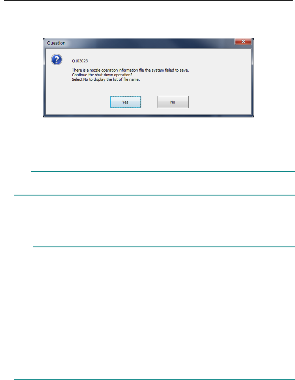
When the main unit shuts down, the following message may appear on the screen.
In this case, nozzle operation information on nozzles collected immediately before the machine
shuts down cannot be saved. Select whether to continue the shut-down operation.
When you select the <Yes> button, the machine shuts down.
Nozzle operation information the system failed to save is not saved in the file. Therefore,
when the machine starts up next time, the information is returned to the previous state.
When you select the <No> button, the machine does not shut down. The name of the nozzle
operation information file the system failed to save is displayed as a text file. Remove the cause of
the file saving failure.
This error may occur due to the followings:
(1) The SSD capacity is insufficient.
Delete or move an unnecessary file(s) to secure the capacity of the drive D.
(2) The file attribute is read-only.
When the file attribute is read-only, the file cannot be written. Cancel the read-only
state.
(3) The system failed to read the file at start-up.
In this case, remove the cause of the file loading failure.
(4) The SSD malfunctions.
If an error occurred although any of the causes (1) to (3) described above does not
apply to your case, the SSD may malfunction.
Contact our service personnel.
Caution
Part 2 Detailed Description of Each Function Chapter 12 Handling the Optional Devices
12-133
12.18 R-ATC Plate
An R-ATC unit is attached on an RS-1R instead of an ATC unit.
The R-ATC unit has the structure that allows its slide plate section to be replaced with another one,
and this allows the slide plate to be replaced according to a nozzle to be used.
The following two slide plates are provided: a standard plate is attached on the machine by
default.
- Standard plate (ATC0001): its hole assignments are the same as those of the ATC unit of an
RS-1.
- Optional plate (ATC0002): this plate has an ATC hole that allows a very large type 1-nozzle
to be attached on the ATC.
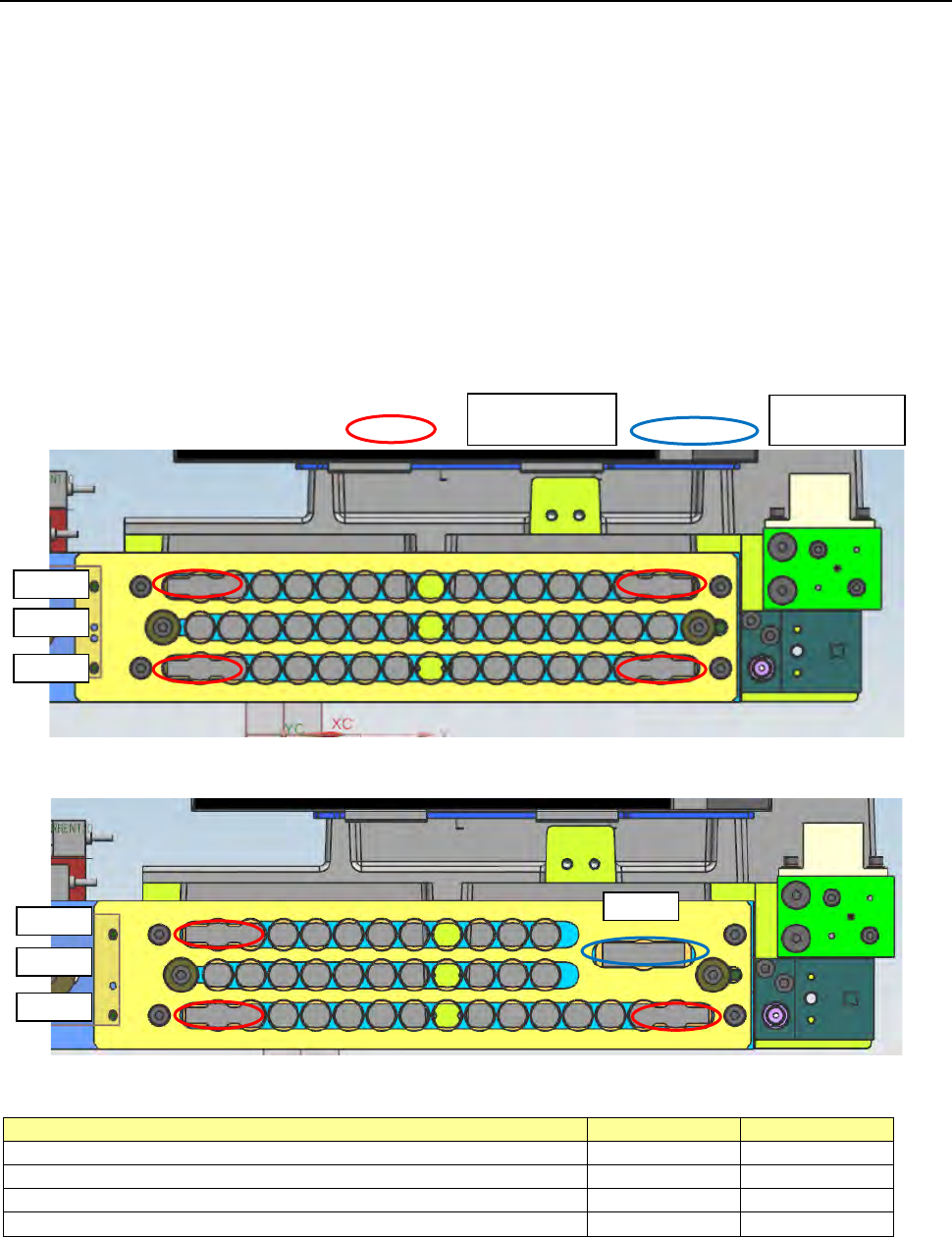
The shape of each plate is shown below.
[Standard plate]
[Optional plate]
The number of holes of each plate is shown in the table below.
Nozzle hole type
Standard plate
Optional plate
Small type nozzle hole Longer side: up to 10 mm
41
34
Large type nozzle hole (*1) Longer side: up to 23 mm
4
3
Very large type 1-nozzle hole (*2) Longer side: up to 30 mm
0
1
Total
45
38
*1 A small type nozzle can be attached on the large type nozzle hole.
*2 Both a small type nozzle and a large type nozzle can be attached on the very large type 1-nozzle
hole.
For large type
nozzle holes
For a very
large type
1 ~ 15
16 ~ 30
31 ~ 45
1 ~ 15
16 ~ 26
27 ~ 37
38
Part 2 Detailed Description of Each Function Chapter 12 Handling the Optional Devices
12-134
12.19 Gripper Nozzle
This nozzle is designed to pick up and/or place on a board a component whose top has no
picked-up area, and it is available to laser and vision recognition.
12.19.1 Features
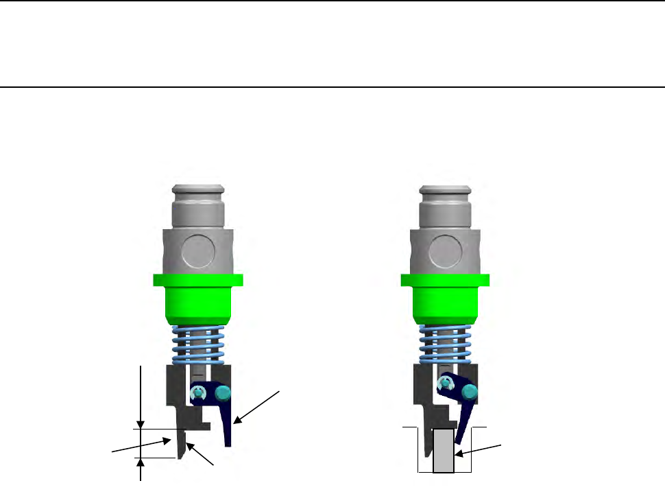
The gripper nozzle uses its “fixed arm” and “swing arm” together exclusively to pick up and/or
place a component whose topside has no picked-up area from the component side. Its grip
strength is appropriate enough to pick up/place a component stably.
① Fixed arm
② Swing arm
Position against a
component is pushed
Length of a lug
①
②
Component