RS-1_instruction manual.pdf - 第277页
Part 1 B asic O peration Chapter 2 Pr oduction 2- 166 Cycle St op When you pre ss the “Cycle Stop” but ton on the main menu, an d the Cycle Stop ic on appears o n the event disp lay view , the system ent ers Cycle St op …
Part 1 Basic Operation Chapter 2 Production
2-165
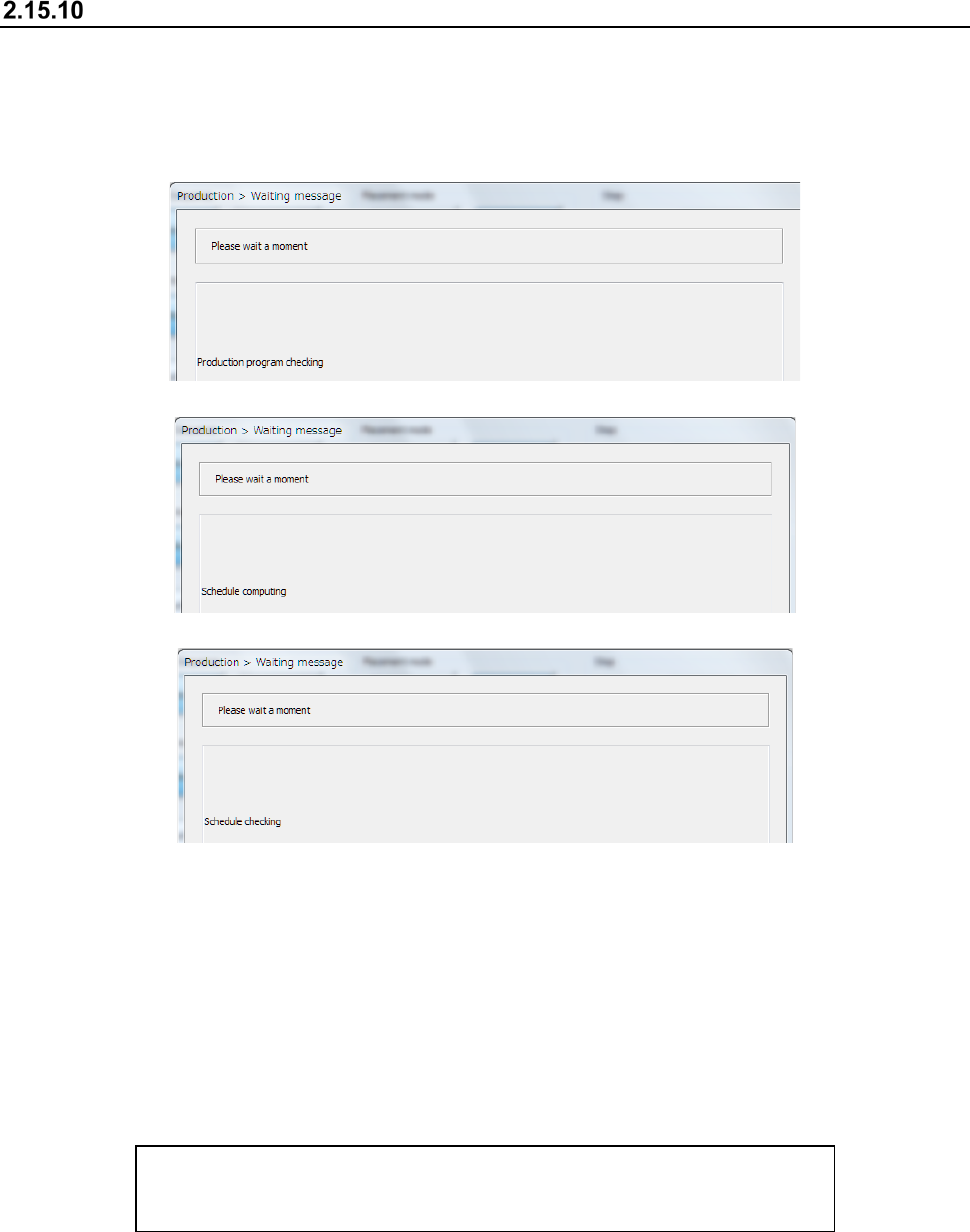
Checking before PWB production starts
When you press the <START> switch of the operation panel to start PWB production, the system
checks a production program, creates a master schedule, and then check the master schedule in
order to judge that it can start PWB production.
- Checking a production program
- Creating a schedule
- Checking the schedule
If a warning is issued as a result of a production program check, the system displays the description
of the warning on the list. (Up to 100 warnings)
If the total number of errors and warnings such as an “incomplete production program” reaches 100,
the system aborts the check and then displays the list immediately.
If the system detects an error or the number of warnings reaches 100, the system cannot start PWB
production.
If no error occurs and the number of warnings does not reach 100 yet, you can start PWB
production by pressing the <START> switch again.
The list of errors or warnings is displayed in the following format:
Data name, error message
(Example) Component, The specified nozzle (7500) has not been set.
Part 1 Basic Operation Chapter 2 Production
2-166
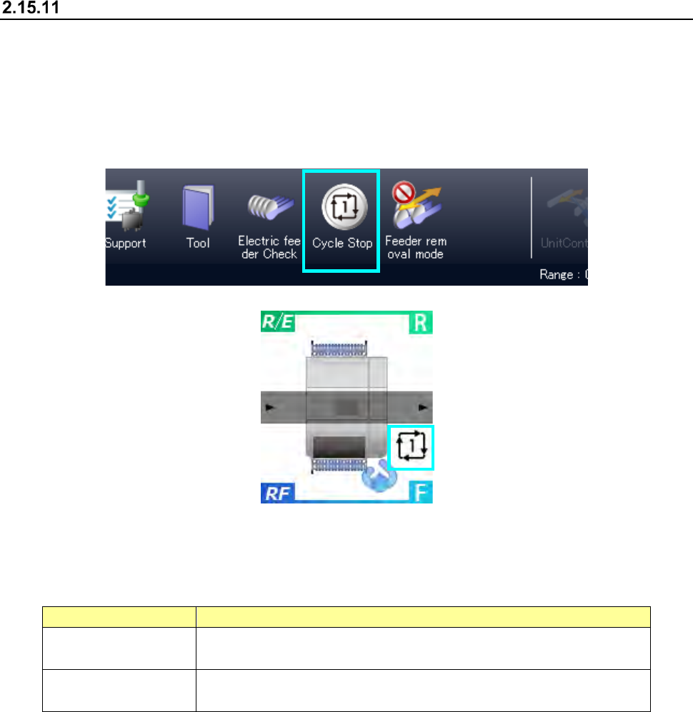
Cycle Stop
When you press the “Cycle Stop” button on the main menu, and the Cycle Stop icon appears on the
event display view, the system enters Cycle Stop mode.
In Cycle Stop mode, the system finishes PWB production with ejecting a board when it finishes
placing a component(s) on the PWB that is being produced.
This is handled as normal termination of PWB production.
When you press the <Cycle Stop> switch again in Cycle Stop mode, Cycle Stop mode is canceled.
You can specify when to terminate PWB production in Cycle Stop mode by specifying the
operation option “Action on cycle-stop” on the “Production (Function)” tab invoked from the
“Operation option” screen.
Menu item
Description
Do not eject PWB. Stops PWB production temporarily without feeding a board after placing all
components on the board.
Eject all WIP PWBs. After the system continues PWB production until it ejects all PWBs on which
all components are placed, it ejects the PWBs to finish the PWB production.
Part 1 Basic Operation Chapter 2 Production
2-167
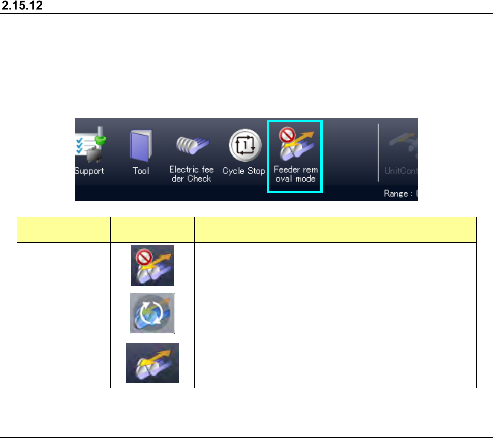
Feeder insertion/removal mode
Every time you press the <Feeder insertion/removal mode> button on the main menu during PWB
production, the operation mode is switched between Normal mode and Feeder insertion/removal
mode.
When you remove a feeder in Normal mode during PWB production, the system pauses. When
you remove an RF feeder in Feeder insertion/removal mode during PWB production, the system
does not pause.
State
Displayed
button
Description
Normal mode
Insertion/removal of a feeder during PWB production is
prohibited, and production is paused when a feeder is
removed.
During mode
transition
The system is entering Feeder insertion/removal mode.
While this icon is displayed, the system operates in the
previous state.
Feeder
insertion/removal
mode
An RF feeder can be removed during PWB production.
In Feeder insertion/removal mode, the ZA-axis height is
adjusted under the category 12 or higher.
The feeder float sensors 2 and 3 are ignored.
2.16 FCS
When you select the “Maintenance” button on the main menu, and then the [FCS] command, the
“FCS Setup” screen appears.
The system can automatically measure the total placement offset value to maintain the component
placement accuracy that is ensured at delivery of the machine.
For details, refer to the “RS-1/RS-1XL/RS-1R FCS (Flexible Calibration System) Instruction
Manual”.