RS-1_instruction manual.pdf - 第967页
Part 2 D etaile d Descript ion of E ach Functi on Chapter 12 Handling th e Optional Device s 12 - 83 12.13.4 Operation option 12.13.4.1 Production (Action) When you select the “ Actio n ” tab from the “ Prod ucti on ” ta…
Part 2 Detailed Description of Each Function Chapter 12 Handling the Optional Devices
12-82
12.13.3.2 Load nozzle check
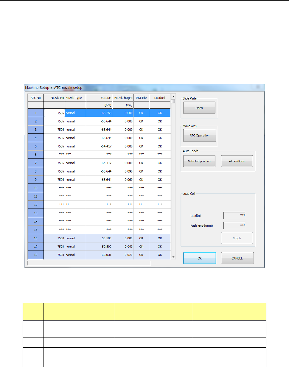
After the machine recognizes a nozzle on the “ATC nozzle setup” screen, it push in the nozzle onto
the load cell 0.1 mm by 0.1 mm until the pushing distance reaches the value specified in the “Push
length” field, and then it checks to see if the measured load is within the threshold value range to
inspect the sliding state (this is to be displayed in the “Load Cell” column).
Note that imposed load is checked for standard nozzles whose number is from 7500 to 7509 and
7680, and low load control nozzles No. 76*1, 76*2 and 76*3.
The machine automatically runs a simulation to check to see if all load of low load control nozzles
within the load input range can be corrected.
Nozzles for which the machine runs a load check and the threshold value range for checking load
are described in the table below.
No. Nozzle number
Push length to be
checked (mm)
Threshold value for
checking (%)
1
7500 to 7505,
7509 and 7680
1.5 Theoretical value ± 50
2
7506, 7507 and 7508
1.5
Theoretical value ± 40
3
76*1 and 76*2
4.5
Theoretical value ± 40
4
76*3
4.5
Theoretical value ± 40
Part 2 Detailed Description of Each Function Chapter 12 Handling the Optional Devices
12-83
12.13.4 Operation option
12.13.4.1 Production (Action)
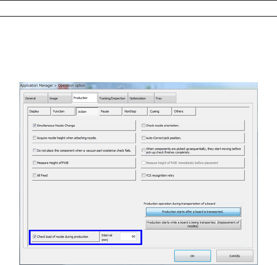
When you select the “Action” tab from the “Production” tab displayed on the “Operation option”
screen, and then place a checkmark in the “Check load of nozzle during production” check box, the
machine reacquires load data of a low load nozzle to be used in PWB production when production
starts and every time the specified time passes (specified in the “Interval” field) during production (to
be precise, when a board is load to the machine).
As a result, the machine can always control load according to a load profile appropriate for the
nozzle condition.
Part 2 Detailed Description of Each Function Chapter 12 Handling the Optional Devices
12-84
12.13.5 Program Editor
12.13.5.1 Load control setting
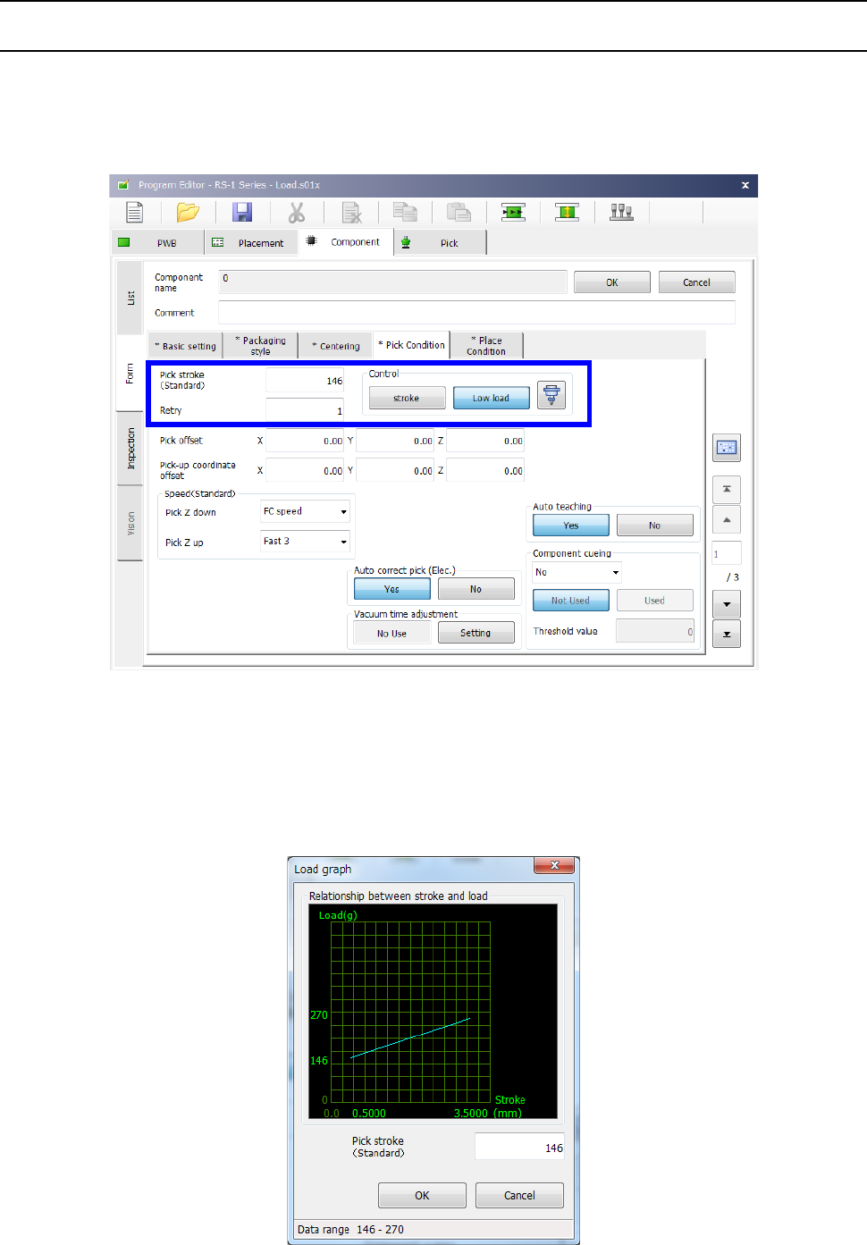
When the selected nozzle is to be used to control load, the “Control” button displayed on the “Pick
Condition” tab and the “Place Condition” tab allows you to select whether to control load or not.
When you select the <Low load> button, the input unit for the menu items “Picking stroke” and
“Placing stroke” is changed from “mm” to “g.”
When the selected nozzle is to be used to control low control, the graph button is enabled on the
screen. When you press this graph button, the graph showing the relation between the push-in
amount (stroke) and the load value appears on the screen.
The input lower limit and the input upper limit of the push-in amount (stroke) are displayed on the
horizontal axis.
The input lower limit and the input upper limit of the stroke (load) are displayed on the vertical axis.