RS-1_instruction manual.pdf - 第884页
Pa r t 2 Det ai l ed Des c r i pti on o f Ea c h Fu nc ti on Chapte r 1 1 S el f - diagnosis Func ti on 11 - 26 Rec or d sa vin g func ti on Diagnostic r ecord file The di agnos ti c r ecor d fi l e sav es t he self - di…
Part 2 Detailed Description of Each Function Chapter 11 Self-diagnosis Function
11-25
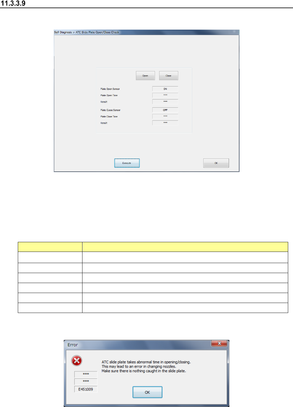
ATC slide plate open/close check
When you select [ATC slide plate] in the self-diagnosis menu, the ATC slide plate open/close
check dialog appears.
When you press the <Open> button, the ATC slide plate of the corresponding bank is opened.
When you press the <Close> button, the ATC slide plate of the corresponding bank is closed.
The dialog box is closed by <OK>.
Specify a bank to be checked and press <Exec>, and an ATC slide plate open/close check is
executed.
Item
Description
Plate open sensor Sensor status when the ATC slide plate is opened
Plate open time Time required to open the ATC slide plate
Check result It is displayed as OK or error whether the plate open time is appropriate.
Plate close sensor Sensor status when the ATC slide plate is closed.
Plate close time Time required to close the ATC slide plate
Check result It is displayed as OK or error whether the plate close time is appropriate.
When an ATC slide plate open/close error occurs, the following message is output.

Part 2 Detailed Description of Each Function Chapter 11 Self-diagnosis Function
11-26
Record saving function
Diagnostic record file
The diagnostic record file saves the self-diagnosis record for one month in the CSV format. The
data to be saved is as follows.
Record item
Description
Component change record
Replacement component information
Date of replacement completion
Error occurrence record
Date of error occurrence
Device of error source
The default diagnostic record saving folder is D: JUKI¥LOG¥Sifc.
Management of diagnostic record file
The SSD of the main unit stores the diagnostic record file for the past one year.
This record file can also be saved in the network shared folder specified by the user. (The SSD
of the main unit cannot be specified.)
Part 2 Detailed Description of Each Function Chapter 12 Handling the Optional Devices
12-1
Handling the Optional Devices
12.1 Feeder types
Refer to the Instruction Manual of each type of feeder for how to handle it.
This chapter describes hot to attach each type of feeder onto the machine.
12.1.1 RF series Electric tape feeder
12.1.1.1 Mounting
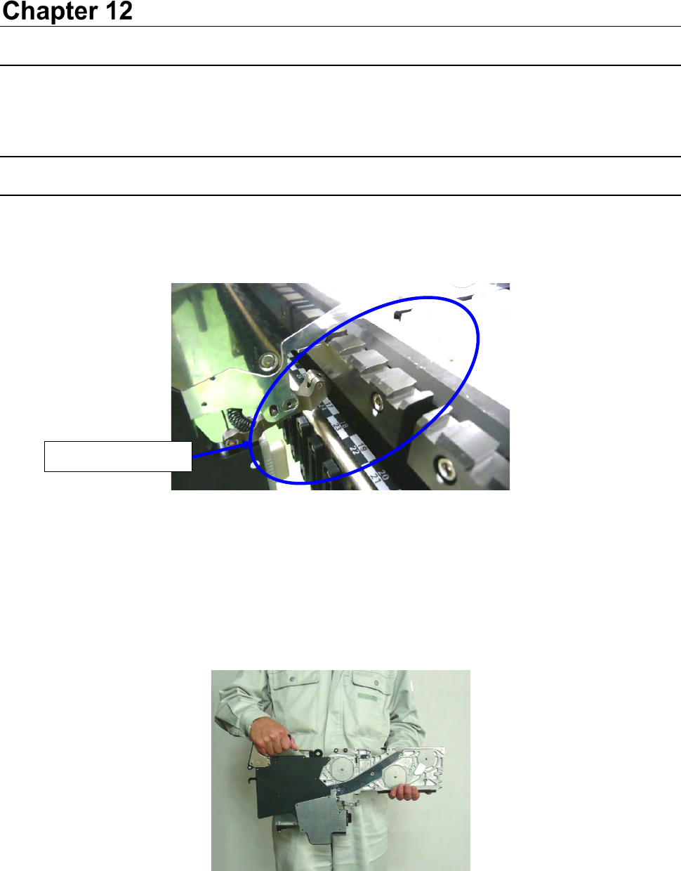
(1) Check to see if there is not any foreign substance such as an element on the following places:
fixed surface of the tape feeder, the topside of the feeder bank of a mounter, and the closely fit
section of connectors.
Figure 12.1-1
* Be sure to check to see if there is no foreign substance such as a component and dust in the
grooves of the sections A and B.
If any foreign substance is caught between thee grooves, the Guide pins (R) (F) are damaged
and it may lower the precision of the component supply position.
(2) Grasp the grip with one hand, support the slide rail with another one, and then attach the
feeder on the bank.
Figure 12.1-2
No foreign substance