RS-1_instruction manual.pdf - 第906页
Part 2 D etaile d Descript ion of E ach Functi on Chapter 12 Handling th e Optional Device s 12 - 22 * T o use a TR5SNX or TR5 DNX that has bee n remod el ed a lready and whose software h as been upgraded with an RS -1 /…
Part 2 Detailed Description of Each Function Chapter 12 Handling the Optional Devices
12-21
Work procedures
① In case of TR8SR, please open the feeder cover of RF08AS and insert it in rear lanes 1, 10,
20 lane.
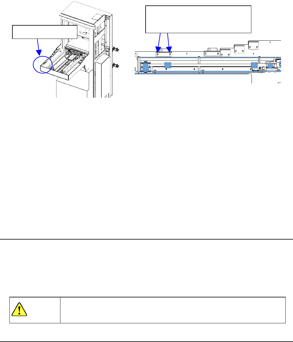
② If the feeder cover you have opened is not detected, gradually lower the feeder float sensor
on the TR8SR side to a position where the opened cover is detected.
③ Insert 8 mm feeder, TR8SR to rear 1st, 10th, 20th and it has a play of the rail when you pull
out the feeder.
④ If incorrect detection occurs, gradually raise the feeder float sensor on the TR8SR side to a
position where no incorrect detection occurs.
⑤ Perform the work stated in step ① again to check that the feeder cover open is detected.
Normally, perform steps ① and ③. If the re-adjustment is needed, perform also steps ②,
④, and ⑤.
Finally, make the setting “MTS assembly position offset”.
12.3.5 Removing the TR8SR
① Stop the operation of the machine.
② Install the casters to float up the adjuster feet from the installation surface.
③ Gradually pull out the TR8SR so that it is not in contact with the internal part of the machine to
prevent part breakage.
④ Close the air valve of the main unit once, and then disconnect the communication cable,
power cable, and air tube.
WARNING
If the machine is operated with the opening of the safety cover opened, your
hand or body may enter the machine in operation accidentally, causing serious
accident.
12.3.6 Setting up the matrix tray server (TR5SNX or TR5DNX)
This machine allows you to select a TR5SNX or a TR5DNX as a matrix tray server (MTS).
Refer to the “INSTRUCTION MANUAL” supplied with the MTS for details such as how to handle it
or how to install it on the machine.
To install a TR5SNX or a TR5DNX that was installed on another machine model onto an RS-1/1R, it
has to be remodeled, the MTS software has to be upgraded, the setting of the DIP switch has to be
changed, and the stopper has to be removed and/or attached on it. If any of this is not performed,
the RS-1 stops urgently when you turn it on.
Contact our Service department for remodeling or upgrading of the MTS.
Feeder float sensor
When adjusting the sensor height,
loosen the screws slightly and
adjust the height gradually.
Part 2 Detailed Description of Each Function Chapter 12 Handling the Optional Devices
12-22
* To use a TR5SNX or TR5DNX that has been remodeled already and whose software has been
upgraded with an RS-1/1R or another machine model, follow the instructions described in
Sections 12.3.7 and 12.3.8.
To avoid any accident caused by sudden activation of the machine, turn
off the power.
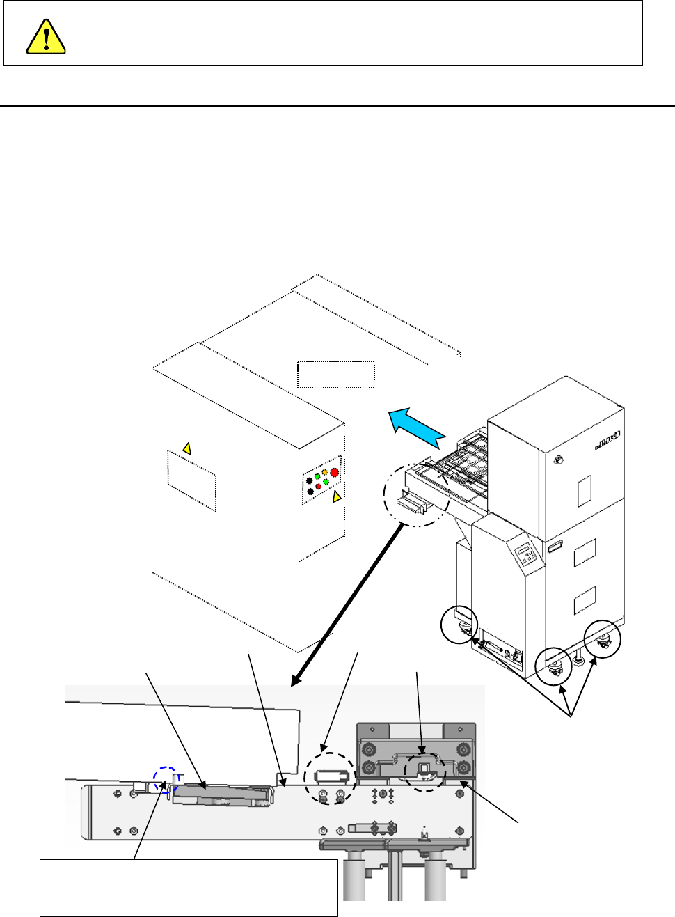
12.3.6.1 How to install
(1) Move down the rear bank of the main unit.
(2) Adjust the caster adjusters 1 of the MTS so that the reference side of the bank support 2 of
the main unit can be aligned with the top side 3 of the joint block of the MTS to level them.
(3) Turn the caster adjusters only on the front side of the MTS so that the topside 3 of the joint
block will be aligned with the upper edge of the guide roller (approximately ± 3 mm).
(4) While the safety cover is closed, install the MTS into the machine main unit gently from the
rear side of the main unit.
(5) Confirm that the MTS has been inserted to the rear of the main unit, and then move up the
bank.
Upper edge of the
roller guide
Mechanical
valve
CAUTION
Mounter
①
③
②
Adjust the caster adjusters so that the height of
this part of the joint block topside can be the same
as that of the top edge of the guide roller
Topside of the
joint block
Bank switch
Part 2 Detailed Description of Each Function Chapter 12 Handling the Optional Devices
12-23
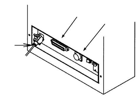
(6) Connect each cable and the air tube to the “Power connector for the MTS,” “Interface
connector” and the “φ6 tube take-up port for the MTS” provided on the interface panel on the
right side of the mounter.
(7) Turn on the power supply of the matrix tray server, and set the menu items "Device enable"
and " MTS position offset” invoked from the “Machine Setup” screen.
①
②
③
TR5SNX/5DNX
①
Power connector for the MTS
② Interface connector for the MTS
③ φ6 tube take-up port for the MTS