RS-1_instruction manual.pdf - 第926页
Part 2 D etaile d Descript ion of E ach Functi on Chapter 12 Handling th e Optional Device s 12 - 42 12.7.2.3.3 Not es on a BOC mark When the out er X - dime nsion of a multi - plane mat rix or non - matrix boar d exce e…
Part 2 Detailed Description of Each Function Chapter 12 Handling the Optional Devices
12-41
12.7.2.3 BOC mark
12.7.2.3.1 Mark teaching
When the machine teaches a BOC mark, it clamps a board. The first BOC mark is taught when
the board is clamped at the stopper position. The second BOC mark is taught when the board is
clamped with the HMS.
You can clamp a board from the screen “Pwb conveyor.”
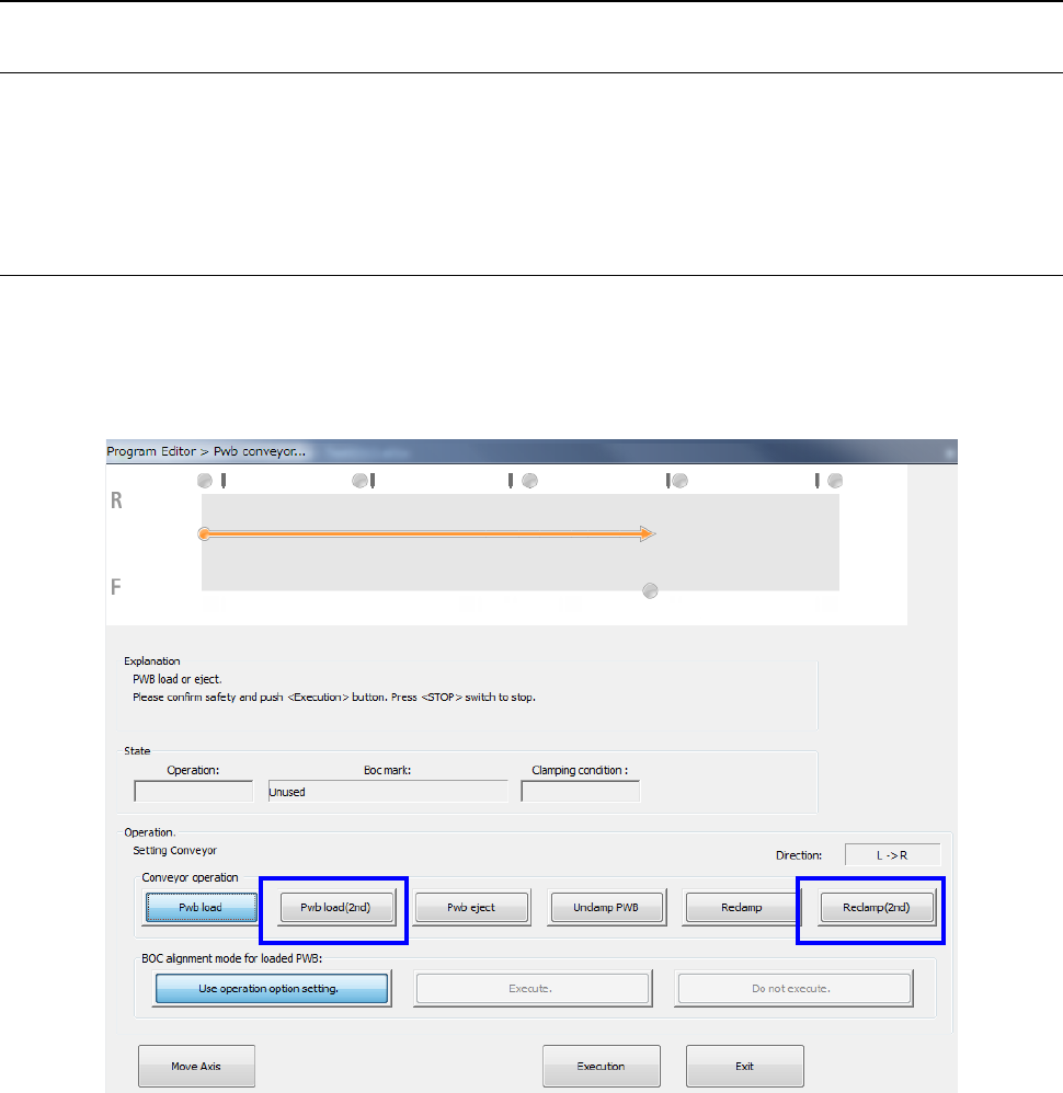
12.7.2.3.2 Pwb conveyor
To clamp a board at the stopper position on the “Pwb conveyor” screen, select the <Pwb load>
button as conventionally.
To clamp a board in the second component placement area with the HMS, select the <Pwb load
(2nd)> button or the <Reclamp (2nd)> button.
Part 2 Detailed Description of Each Function Chapter 12 Handling the Optional Devices
12-42
12.7.2.3.3 Notes on a BOC mark
When the outer X-dimension of a multi-plane matrix or non-matrix board exceeds the regulated
size and circuits are divided in the X direction, you can select a mark for each circuit, but the
machine cannot produce any PWB. The machine displays the error before production starts.
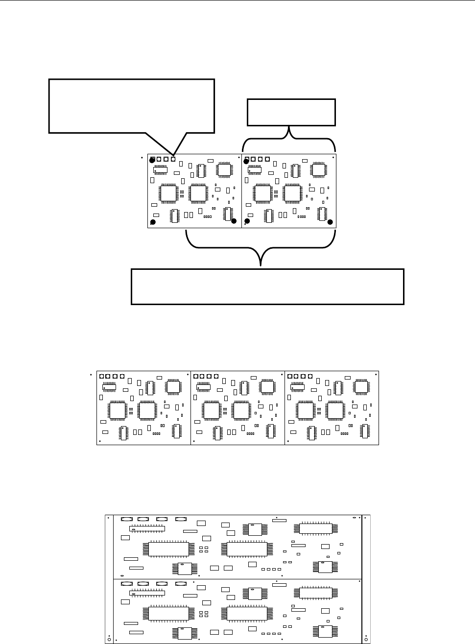
An example where the board X-dimension is 900 mm, the long-sized board division position is at a
position 650 mm and a board is divided into two in the X direction is shown below.
When the outer X-dimension of a board exceeds 650 mm and the board is divided in the X
direction as shown below, a BOC mark is located outside the area where a board is to be clamped
for the first time. Therefore, an error is detected before production starts.
When the outer X-dimension of a board exceeds 650 mm and the board is divided in the Y
direction as shown below, any error does not occur even though there is a BOC mark outside the
area where a board is to be clamped for the first time. (You have to enter the second BOC mark.)
Since the mark position exceeds
the first clamping area 650 mm, an
error is detected before production
starts.
Area where a component is placed when a board is
clamped for the first time: 650 mm
450mm

Part 2 Detailed Description of Each Function Chapter 12 Handling the Optional Devices
12-43
12.7.2.4 Limitations on the supported long-sized board
- The machine cannot track a component placement of a long-sized board with a camera
during Try Run or Dry Run operation.
- The machine can track a component placement position of a long-sized board as long as the
corresponding head can move to its coordinates when the [Placement tracking] command is
executed from the “Support” menu.
The machine cannot track any coordinates to which no head can move due to the board
clamping condition.
- When you optimize a production program for a long-sized board by selecting the optimization
option “Assign in optimized order” and optimizing the program, the machine cannot perform
optimization with taking two clamping operations into consideration. Select the option
“Assign in input order of Production Program File” to optimize a program.
- If component placement positions of a circuits are arranged over two areas: area clamped for
the first time and area for the second time, set a bad mark position in the first component
placement area.
- When an MTC is used with the machine, the maximum X-dimension of a board that can be
transported is limited.