RS-1_instruction manual.pdf - 第328页
Part 1 Basic Operat ion Chapter3 D aily maintenance 3- 36 3.5 Part s Recommended to Be Re placed on a Regular Basi s The compo nents that hav e to be replaced on regula r basis due to wear or deg radation other than expe…

Part 1 Basic Operation Chapter3 Daily maintenance
3-35
No Part number Part name Q’ty Unit
When to
replace
(guideline)
Remarks
(Year)
31 40189000 NOZZLE_ASSEMBLY_7500_CVS -
Head
0.9 No RFID tag (for RS-1)
32 40189001 NOZZLE_ASSEMBLY_7501_CVS - 0.9 No RFID tag (for RS-1)
33 40189002 NOZZLE_ASSEMBLY_7502_CVS - 0.9 No RFID tag (for RS-1)
34 40189003 NOZZLE_ASSEMBLY_7503_CVS - 0.9 No RFID tag (for RS-1)
35 40189004 NOZZLE_ASSEMBLY_7504_CVS - 0.9 No RFID tag (for RS-1)
36 40189005 NOZZLE_ASSEMBLY_7505_CVS - 0.9 No RFID tag (for RS-1)
37 40189006 NOZZLE_ASSEMBLY_7509_CVS - 0.9 No RFID tag (for RS-1)
38 40186979 NOZZLE_ASSEMBLY_7680 - 0.9 No RFID tag (for RS-1)
39 40222517 NOZZLE_ASSEMBLY_7509_RFID - 0.9
WITH RFID TAG
(for RS-1R) *1
40 40222518 NOZZLE_ASSEMBLY_7500_RFID - 0.9
WITH RFID TAG
(for RS-1R) *1
41 40222519 NOZZLE_ASSEMBLY_7501_RFID - 0.9
WITH RFID TAG
(for RS-1R) *1
42 40222520 NOZZLE_ASSEMBLY_7502_RFID - 0.9
WITH RFID TAG
(for RS-1R) *1
43 40222521 NOZZLE_ASSEMBLY_7503_RFID - 0.9
WITH RFID TAG
(for RS-1R) *1
44 40222522 NOZZLE_ASSEMBLY_7504_RFID - 0.9
WITH RFID TAG
(for RS-1R) *1
45 40222523 NOZZLE_ASSEMBLY_7505_RFID - 1
WITH RFID TAG
(for RS-1R) *1
46 40222524 NOZZLE_ASSEMBLY_7506_RFID - 1
WITH RFID TAG
(for RS-1R) *1
47 40222525 NOZZLE_ASSEMBLY_7507_RFID - 1
WITH RFID TAG
(for RS-1R) *1
48 40222526 NOZZLE_ASSEMBLY_7508_RFID - 1
WITH RFID TAG
(for RS-1R) *1
49 40222543 NOZZLE_ASSEMBLY_7500_CVS_RFID - 0.9
WITH RFID TAG
(for RS-1R) *1
50 40222544 NOZZLE_ASSEMBLY_7501_CVS_RFID - 0.9
WITH RFID TAG
(for RS-1R) *1
51 40222545 NOZZLE_ASSEMBLY_7502_CVS_RFID - 0.9
WITH RFID TAG
(for RS-1R) *1
52 40222546 NOZZLE_ASSEMBLY_7503_CVS_RFID - 0.9
WITH RFID TAG
(for RS-1R) *1
53 40222547 NOZZLE_ASSEMBLY_7504_CVS_RFID - 0.9
WITH RFID TAG
(for RS-1R) *1
54 40222548 NOZZLE_ASSEMBLY_7505_CVS_RFID - 0.9
WITH RFID TAG
(for RS-1R) *1
55 40222549 NOZZLE_ASSEMBLY_7509_CVS_RFID - 0.9
WITH RFID TAG
(for RS-1R) *1
56
40222542 NOZZLE_ASSEMBLY_7680_RFID - 0.9
WITH RFID TAG
(for RS-1R) *1
57
40223138
STYLUS_PEN
1(2)
Stylus
-
For RS-1R
58
40223139
LONG_KEYHOLDER
1(2) -
For RS-1R
*1 RFID tags are common to all RFID readers (whose destinations are Japan, Europe and the U.S.A.).
Part 1 Basic Operation Chapter3 Daily maintenance
3-36
3.5 Parts Recommended to Be Replaced on a Regular Basis
The components that have to be replaced on regular basis due to wear or degradation other than
expendables are shown in the table below.
Regardless of whether a device is described in the table below or not, all air devices have to be
replaced with new ones if oil or water is mixed into the air of them.
Contact our Service department or dealer for how to replace a component with a new one.
No. Part number Part name Quantity Device
When to
replace
(guideline)
(Year)
Remarks
1 PF901010000 FILTER ELEMENT 1 Cover 1
Pressure difference
between the front and
the rear: 0.1 MPa
2 PF901006000 FILTER ELEMENT B 1 Cover 1
Pressure difference
between the front and
the rear: 0.1 MPa
3 EZ175664711
BATTERY PACK
(BS06A-H24/2.5L)
1
Electric
section
3
4 40182492 UPPER_EDGE 1 Bank 1
5 40182493 LOWER_EDGE 2 Bank 1
6 40138045
VACUUM PUMP
MAINTENANCE KIT
1 Pump 0.9
* One year = 6,600 hours (22 hours/day × 300 days/year)
3.6 Used Grease and Oil
No Part No. Part name Capacity Remarks
1 MDFRX1001L0 DEFRIX OIL NO1 800ml
2 40032449 6459 GREASE N 400g A grease gun is used.
3 40127626 GREASE_GUN
4 40127627 GREASE_GUN_NOZZLE
5 40046643 CG2 GREASE 2.5mg Injector type
6 40094361 NSL GREASE 80g A hand grease pump is used
7 40098975 NSK_HGP
One-touch-mounting small
bellow-type container of grease
8 40106055 FLEXIBLE NOZZLE
For an XY ball screw that can be
attached onto a No. 6 grease gun
9 EZ764002555 AFF+400 400g
Part 1 Basic Operation Chapter3 Daily maintenance
3-37
3.7 How to replace the periodic replacement parts
* It is very dangerous to replace the cutter blade. To replace the cutter blade, ask our service
division or agent to replace it. For details, make inquiries at the information service.
The pressure may be lowered due to abrasion of the following parts:
<List of consumable parts>
Part number of the consumable parts kit: 40138045
Where to check
Quantity
of use
What to check
How to
check
Cup packing 2 Abnormal abrasion, hardening, and crack Visual check
Cylinder gasket 2 Deformation, hardening and crack Visual check
Air suction/release valve 2 Deformation, hardening and chip Visual check
O-ring S-647 2 Deformation, abrasion, hardening and crack Visual check
Head gasket 2 Deformation, hardening and crack Visual check
Check/
replacement
Replacement of stylus pen and long key holder
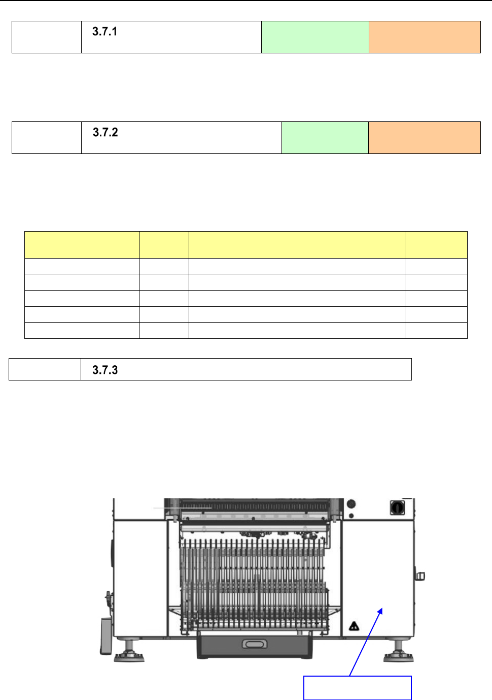
Preparation for replacing the vacuum pump
1) Check to see if the vacuum pump does not operate. (After the pump operates, the inside of the
pump gets hot. Therefore, leave the pump for approximately 30 minutes after it stops, and then
start replacing it only after making sure that it is cooled down.)
2) Remove the front lower right cover of the machine main unit.
Check/
replacement
Replacement of a cutter
unit
Tools to be used:
Hexagon wrench and
driver
When to replace
(guideline): One year
Check/
replacement
Replacement of a part of a
vacuum pump
Tools to be used:
Hexagon wrench
and screwdriver
When to replace
(guideline): One year
Cover (Screw × 4)