RS-1_instruction manual.pdf - 第667页
Pa r t 2 D et ai l ed Des c r i pt i o n of Ea c h F unc t i o n Chapte r 6 G e neral - Purpose Vision Co mpone nt 6- 36 ③ When t he e nd posi tion o f the firs t ball i s ( - 6.0 m m, - 5. 0 m m) in t he exam p le in “ …
Part 2 Detailed Description of Each Function Chapter 6 General-Purpose Vision Component
6-35
Bottom View
1
3
2
4
5
1
2
3
4
5
6
①
Name
Name an element group to be handled. When you want to change an element group,
specify its name to edit it.
A name is automatically assigned with serial numbers. Users can change this numbered
name to an alphanumeric name (up to 32 characters).
- In the example, the numbered name is used.
②
First element position
Specify the position (X, Y) and direction (Theta) of an element group.
As the position, specify the distance (offset) from the center of a component. Normally, the
center of a component is the center of the component outline.
- If the placement coordinates set in Placement data of a production program is not based
on the center of the component outline, you can specify the coordinates of the reference
component center with coordinates different from the center of the component outline.
The figure indicates that the center of the component outline is the center of a
component.
To be precise, the “First element position” is the distance
(offset) from the center of a component to the first element.
The direction (angle) of the element group is basically 0 degrees.
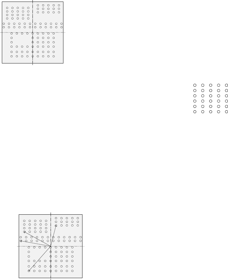
The figure shows the relation between the lines (rows) and
columns.
The first (ball or land) element positions at the coordinates of
the element (ball/land) at the lower left corner.
- This layout of elements is different from that of a standard
BGA component having balls on the outer frame.
The figure shows the first element (ball/land) position of the component shown in the
example above.
For a ball/land element, the center of the first ball/land viewed from the center of a
component becomes the coordinates of the first (ball/land) element.
Line (row) number
Column number
Bottom View
Center of a component (Center of
the component outline)
Bottom View
Center of a component
(Center of the component outline)
Part 2 Detailed Description of Each Function Chapter 6 General-Purpose Vision Component
6-36
③
When the end position of the first ball is (-6.0 mm, -5.0 mm) in the example in “First
element arrangement.”
Offset X : - 6.0
Offset Y : - 5.0
Offset Z : 0 (not used)
Offset Theta: 0
- Normally, enter “0” to each field of the setting item “Tolerance.”
• Next, set the element group arrangement.
To set the arrangement, the setting items “Dimension”(Point, 1D, 2D), and “Count” and
“Pitch” of the “Column” and “Row” are provided.
④
Dimension (Point, 1D, 2D),
For a ball/land element, the dimension is two. Select “2D.”
Note: For arrangement of only one column and one row, specify “2D” also.
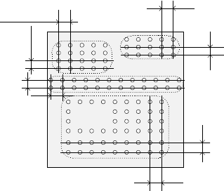
◆ The figure shows the pitch of each element group.
- In the example, the number of lead columns located in the first element group is nine.
Enter “9” to the “Count” field displayed under the setting item “Column.”
Note: For arrangement of only one line, enter “1.”
- When the pitch is 1.5 mm, enter “1.5” to the “Pitch” of the “Column” field.
Note: For arrangement of only one line, enter “1.5” also.
- Normally, enter “0” to the “Tolerance” field.
- Since the number of lead rows located in the first element group is six, enter “6” to the
“Count” field of the “Row” setting item.
Note: For arrangement of only one row, enter “1” to the “Count” field.
- When the pitch is 1.27 mm, enter “1.27” to the “Pitch” field of the “Row” setting item.
Note: For an arrangement of one row only, enter “1.27” to the “Pitch” field too.
- Normally, set “0” to the “Tolerance” field.
Bottom View
Pitch of the “Column” of the third
element group
Pitch of the “Row” of the third
element group
Pitch of the “Row” of the second
element group
Pitch of the “Column” of the
second element group
Pitch of the “Column” of the
fourth element group
Pitch of the “Row” of the fourth element
group
Pitch of the “Row” of the
first element group
Pitch of the “Column” of
the first element group

Part 2 Detailed Description of Each Function Chapter 6 General-Purpose Vision Component
6-37
⑤
Layout inspection
This item is not used by the current version.
⑥
Missing Elements
In the example, there is missing balls (lands) on the first element group. If there is/are a
missing ball(s)/land(s), specify this setting item also in the same manner as that of a
BGA/FBGA.
Up to four blocks of missing balls/lands can be specified per element group.
To specify a block, set the first missing ball/land position of the column and row respectively
and the number of lines having missing balls/lands located continuously in the same manner
when you set those of a BGA/FBGA component.
- If there is no ball/land on three columns from the second column and no balls/lands on
two rows from the fourth row, enter values as shown below:
“Start” of the “Column” field : 2
“Count” of the “Column” field : 3
“Start” of the “Row” field : 4
“Count” of the “Row” field : 2
Note: If there is no ball/land at five or more portions, divide the element group further, then
define those divided element groups.
●
Here, you have finished setting an element group.
● Next, define a recognition element of this element group.
Only one element can be defined per element group.
Even though you define two or more elements, they are handled as “invalid”.
Click the <Add> button in the “Element” setting field.