RS-1_instruction manual.pdf - 第1021页
Part 2 D etaile d Descript ion of E ach Functi on Chapter 12 Handling th e Optional Device s 12 - 137 12.19.3 How to Use (1) In Machine set up, t he gripper nozz le informat ion is read f rom the USB m emory attached to …
Part 2 Detailed Description of Each Function Chapter 12 Handling the Optional Devices
12-136
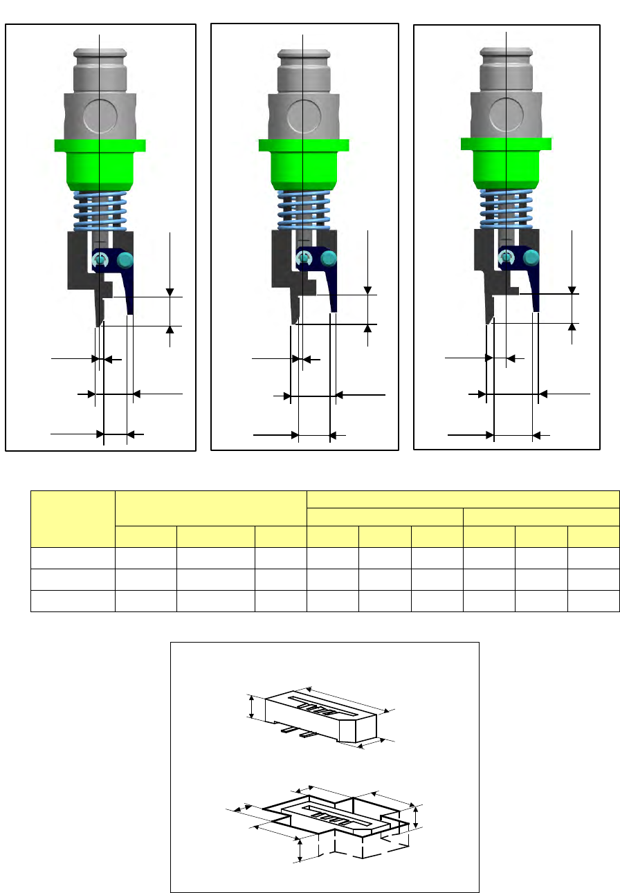
- Applicable component and applicable package size
・Applicable component and package size
Nozzle
number
Applicable components
Packaging style (Dimensions of an embossed part)
Fixed arm side
Swing arm side
X
Y
H
A
B
C
D
E
F
7689
6
~
0.8
~
2.2
5
~
1.5
~
5.6
~
4
~
3
~
5.6
~
2.5
~
7690
6
~
1.8
~
3.2
5
~
1.5
~
5.6
~
4
~
3
~
5.6
~
2.5
~
7691
6
~
2.8
~
4.2
5
~
1.5
~
5.6
~
4
~
3
~
5.6
~
2.5
~
H
X
Y
A
D
E
B
F
C
0.5
4.7
2.8
3.5
No. 7689 nozzle
0.5
5.7
3.8
3.5
No. 7690 nozzle
1.5
6.7
4.8
3.5
No. 7691 nozzle
Part 2 Detailed Description of Each Function Chapter 12 Handling the Optional Devices
12-137
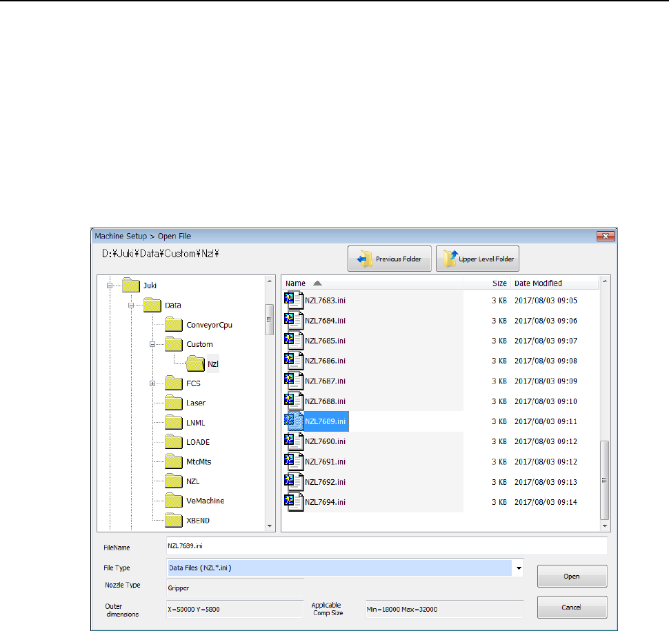
12.19.3 How to Use
(1) In Machine setup, the gripper nozzle information is read from the USB memory attached to
the nozzle.
If any USB memory is not supplied with the purchased special nozzle, or if the USB memory
malfunctions or is lost, check D:¥JUKI¥DATA¥Custom¥Nzl.
* Once you load information, it is stored on the machine, so you do not have to perform this
operation every time you use the machine.
◇ Select the [Read Nzl. data] command from the “File” menu invoked from the “Machine
setup” menu, and load the nozzle information file for a gripper nozzle on the following
dialog box. (See Section 8.3.2.2 “Read Nzl. data (read nozzle data).”)
Part 2 Detailed Description of Each Function Chapter 12 Handling the Optional Devices
12-138
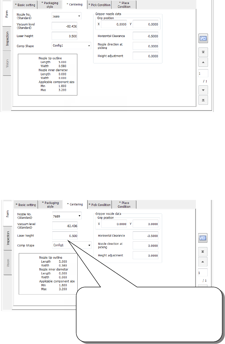
(2) Creating Component data
◇ Example for creating Component data
① Setting the nozzle number
② Entering information for controlling a component position picked up by a gripper nozzle
See ⑤ “Gripper nozzle data” of Section 4.3.5.2.3 (3)“Centering” for details.
③ Laser pos. (position)
Be careful to enter this setting item when you use a gripper nozzle.
Normally, enter the distance from the top of a component to the surface on which laser
beam impinges in the “Laser pos.” field of a nozzle. However, when you use a gripper
nozzle, enter the distance laser is beamed by regarding the tip of the nozzle that is
located at the fixed arm as a reference position.
Specify the distance from the tip of a nozzle to the surface
on which laser beam impinges.
Setting guide: - (component height – 3.5 mm) / 2
Make trivial adjustments of this value
according to a lead position.
Example shown on this screen: - (3.8 – 3.5) / 2
= - 0.15