RS-1_instruction manual.pdf - 第808页
Part 2 D etaile d Descript ion of E ach Functi on Chapter 9 M anual Control 9- 36 9.6.5 .1 Sensor information When you pres s the <Sensor in formation > butt on in the driv er status dia log, the sens or informati …
Part 2 Detailed Description of Each Function Chapter 9 Manual Control
9-35
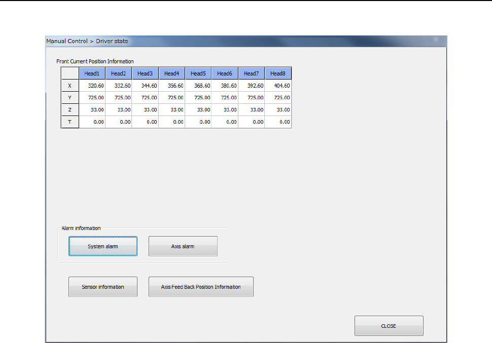
9.6.5 Driver status
When you select [Other] – [Driver status] in the menu, the driver status dialog appears.
(1) Current position information
The coordinates of the current position of each axis and its rotation angle are displayed.
This has no effect on the setting in “Device enable” in Machine setup. The status of units
that are not checked off (not used) is also displayed.
(2) Sensor information
When you press the <Sensor information> button, the sensor information is displayed. Its
details will be described later.
(3) Axis feedback position information
When you press the <Axis feedback position information> button, the axis feedback position
information is displayed. Its details will be described later.
Part 2 Detailed Description of Each Function Chapter 9 Manual Control
9-36
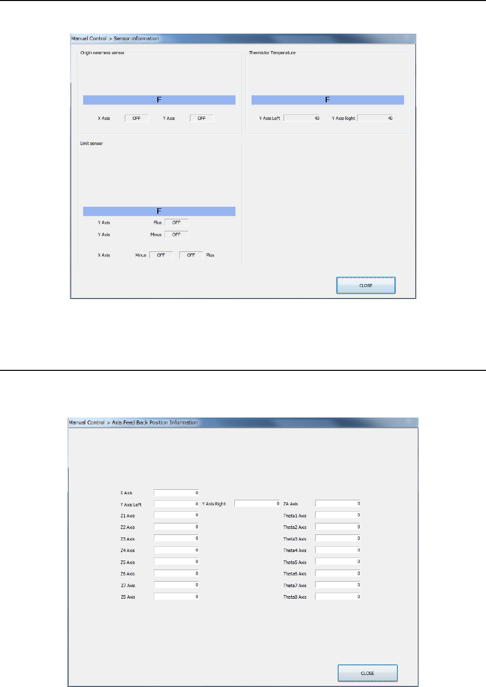
9.6.5.1 Sensor information
When you press the <Sensor information> button in the driver status dialog, the sensor
information dialog appears.
The status of the origin nearness sensor and limit sensor are displayed as ON/OFF, and the
thermistor temperature information is displayed numerically.
9.6.5.2 Axis feedback position information
When you press the <Axis feedback position information> button in the driver status dialog, the
axis fed back position information appears.
Part 2 Detailed Description of Each Function Chapter 9 Manual Control
9-37
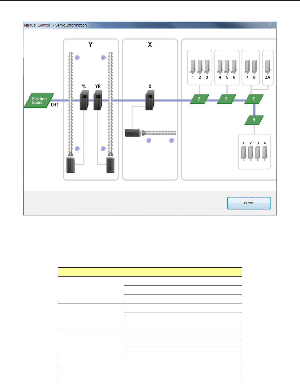
9.6.6 Servo status
When you select [Other] - [Servo status] in the menu, the servo status dialog appears.
(1) Servo statusThe current condition of each servo is displayed here.
A unit at which a servo error occurs is displayed in red.
When you move the cursor over a unit icon or each sensor icon, the corresponding tool hint
appears on the screen.
Unit
Y axis right
Amplifier
Motor
Limit sensor plus/minus
Y axis left
Amplifier
Motor
Limit sensor plus/minus
X axis
Amplifier
Motor
Limit sensor plus/minus
Theta 1 to Theta 4
Z1 to Z8, ZA
Position board