RS-1_instruction manual.pdf - 第734页
Part 2 D etaile d Descript ion of E ach Functi on Chapter 8 Machine Set up 8- 26 ( 2) How to set 1) Delay unit sel ection a) Set the delay unit by radio but ton. b) W he n you select [T ime], the v alue set for P W B tra…

Part 2 Detailed Description of Each Function Chapter 8 Machine Setup
8-25
(1) Setting item
No.
Item
Description
1
PWB
conveyor
Select delay unit (*)
Sets the units for the delay in the PWB conveyor sensor.
2
Sensor delay setting
(*)
Select standard or option to set the delay time.
3 Standard (*)
Sets the values of delay times or lengths for all the
sensors in cut out and punch hole board conveyance to
the same length.
4 Option (*) Sets the above delay for each sensor separately.
5 Ready In delay time (*)
When the OUT sensor is set to ON to detect a board
while a board is being ejected to the post-process device,
the system checks the status of the ReadyIn signal after
the time set in this “Ready In delay time” field passes.
When the ReadyIn signal is set to ON, the system starts
ejecting a board to the post-process device. The range
of the time you can set in the “Ready In delay time” field
is from 0 to 300 seconds.
6
Conveyor motor speed
(*)
“Transferring PWB” sets the board transportation speed
between the IN sensor and the OUT sensor.
“Preceding Process” sets the speed in which the machine
loads a board from the previous process until it finishes
loading the board into it completely (until the IN sensor is
set to OFF).
“Next Process” sets the board transportation speed
between the OUT sensor and the post-process device.
7
Sensor delay when re-
clamp (*)
Sets the STOP sensor OFF timing during re-clamp.
8
Board loading
restriction
Puts the ReadyOut signal in the OFF status after the final
PWB has been drawn into the transport path of the
machine during production.
9
Reduce PWB in
process
Specify whether to carry in the PWB into a buffer other
than the placement station inside the machine.
10
Hold Wait Sensor
active until PWB
moves out (*)
Specify whether to locate the notch on the WAIT sensor
when the production is stopped by the WAIT sensor.
11
ZA-axis operation with
the substrate size for 3
buffers
Specify whether to adjust the ZA-axis height to the highest
one of the positions at which components have been
already placed in the same manner with 1-buffer mode
when the machine is producing a PWB whose size is
applicable to 3 buffers.
12
Short substrate setting
Set the transport operation of a short-sized board.
13
Change of standby
position of a short
substrate
When the board size is smaller than or equal to the size
set in the “Short substrate judgment size” field, you can
cause the board to wait at the WAIT2 sensor position.
14
Short substrate
judgment size
Specify the board size for determining that the board is
short.
* If a production program makes settings of the conveyor, those settings are applied here.
Part 2 Detailed Description of Each Function Chapter 8 Machine Setup
8-26
(2) How to set
1) Delay unit selection
a) Set the delay unit by radio button.
b) When you select [Time], the value set for PWB transport sensor delay is treated as
ms for a delay.
c) When you select [Length], the value set for PWB transport sensor delay is treated
as mm, 1/100 mm or inch for a delay.
2) Sensor delay time setting (standard and option)
a) Select “Standard” or “Option” by pushbutton.
b) When Option is selected, the delay time or length can be set for each sensor.
c) A value of 0 ~ 2500 (ms) or 0 ~ 1000 (mm: Unit is mm) can be set.
d) The value should be 60 ms as standard for a 320 mm notching.
3) Ready In signal delay function
a) A value of 0 to 300 can be set.
4) Conveyor motor speed
a) This speed can be set for transfer of a board (“Transferring PWB”), for loading a
board from the previous process (“Preceding process”) and for ejecting a board
from the post process (“Next process”) respectively.
b) The speed can be set by 4 steps from the combo box.
5) Sensor delay when re-clamp
a) A value of 0 to 5000 (ms) or 0 to 200 (mm: Unit is mm) can be set.
6) Board loading restriction
a) Function ON/OFF can be set from the check box.
7) Reduce PWB in process
a) Function ON/OFF can be set from the check box.
8) Hold Wait Sensor active until PWB moves out
a) Function ON/OFF can be set from the check box.
9) ZA-axis operation with the substrate size for 3 buffers
a) This function can be set to ON/OFF with the check box.
10) Change of standby position of a short substrate
a) This function can be set to ON/OFF with the check box.
11) Short substrate judgment size
a) You can set the size in the range of 50.00 to 300.00 (mm).
Part 2 Detailed Description of Each Function Chapter 8 Machine Setup
8-27
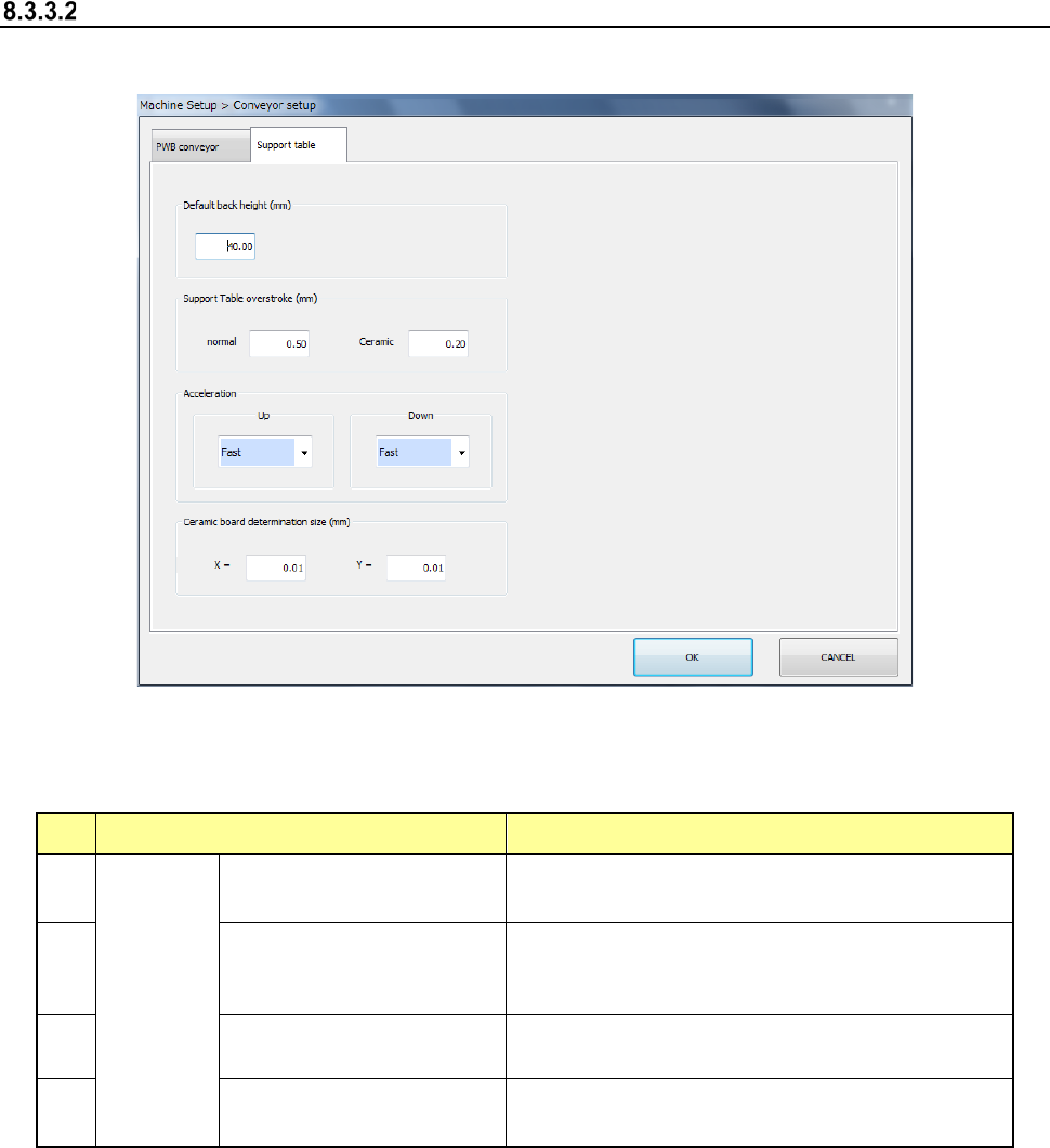
Support table
When you select [Support table], the following screen appears.
When you click each tab, you can specify [PWB conveyor] or [Support table].
(1) Setting item
No. Item Description
1
Support
table
Default back height (*2)
Set the PWB lower limit value of the support
table.
2
Support Table overstroke
(*2) (usually ceramic (*1))
Set the inserting stroke of the support table.
3
Acceleration (*2)
(ascent, descent)
Set the acceleration of the support table.
4
Ceramic board
determination size (X, Y)
Set the ceramic board size.
*1 Stroke in the item of ceramic
When "The ceramic board is used" of production, etc. is checked and the board size (XY)
is less than 150 mm, it is judged that the ceramic board is used and the stroke input to the
item of ceramic is used. As for the PWB other than the ceramic PWB, the stroke input to
the item of ceramic is applied when a PWB size of less than 150 mm and an optional
operation are set. However, a usual stroke is applied for the PWB of 150 mm or more as
for the ceramic PWB.
*2 If a production program makes settings of the conveyor, those settings are applied here.