RS-1_instruction manual.pdf - 第911页
Part 2 D etaile d Descript ion of E ach Functi on Chapter 12 Handling th e Optional Device s 12 - 27 12.4 Handling the IC Co llection B elt 12.4.1 Specifications Compone nts T ypes: QFP , SOP , PLCC, etc. ( Compone nts u…
Part 2 Detailed Description of Each Function Chapter 12 Handling the Optional Devices
12-26
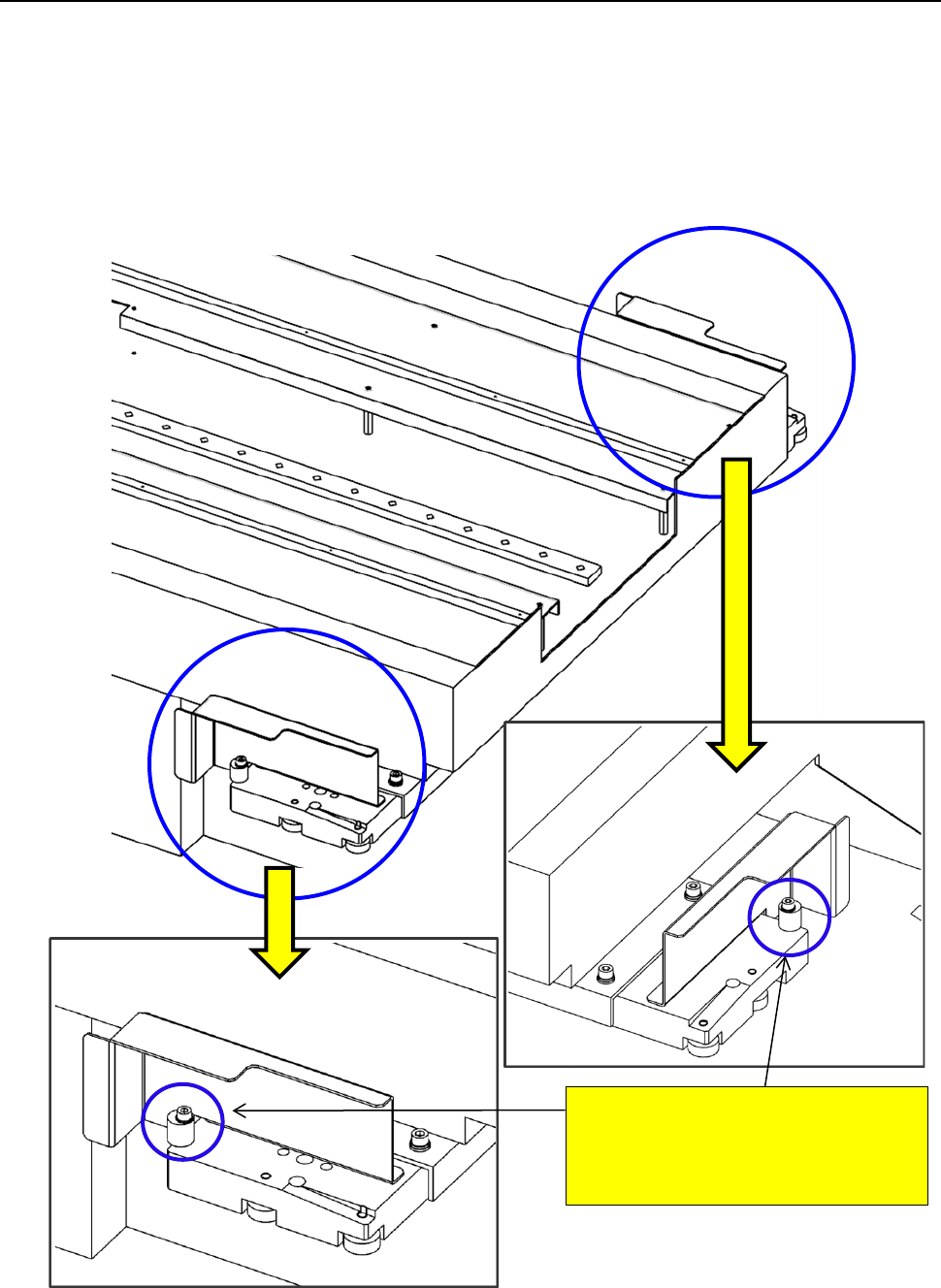
12.3.8 Removing the stopper (TR5SNX/TR5DNX)
You have to remove the stopper from an MTS other than a TR8SR when connecting it to an
RS-1/1R.
Since the stopper is attached on the MTS at the factory, remove it from the MTS when connecting it
to the RS-1/1R. When connecting it to a machine other than an RS-1/1R, attach the stopper on the
MTS.
To use with the RS-1/1R a TR5SNX/TR5DNX that was used in another machine model, follow the
instructions below only after remodeling the MTS and upgrading its software.
<<Stopper>>
RS-1/1R: Remove the stopper.
Machine model other than
an RS-1/1R: Attach the stopper.
Part 2 Detailed Description of Each Function Chapter 12 Handling the Optional Devices
12-27
12.4 Handling the IC Collection Belt
12.4.1 Specifications
Components
Types: QFP, SOP, PLCC, etc. (Components using image recognition device)
Sizes: □10 to □50mm,1.0 to 6.0 mm
Collection
number of IC
9 to 31 pcs (depending on the maximum size of IC to be used.)
Feeding mount of
belt
15 to 55 mm (by 5 mm)
(Set the rotary switch to manual mode according to the maximum size of IC)
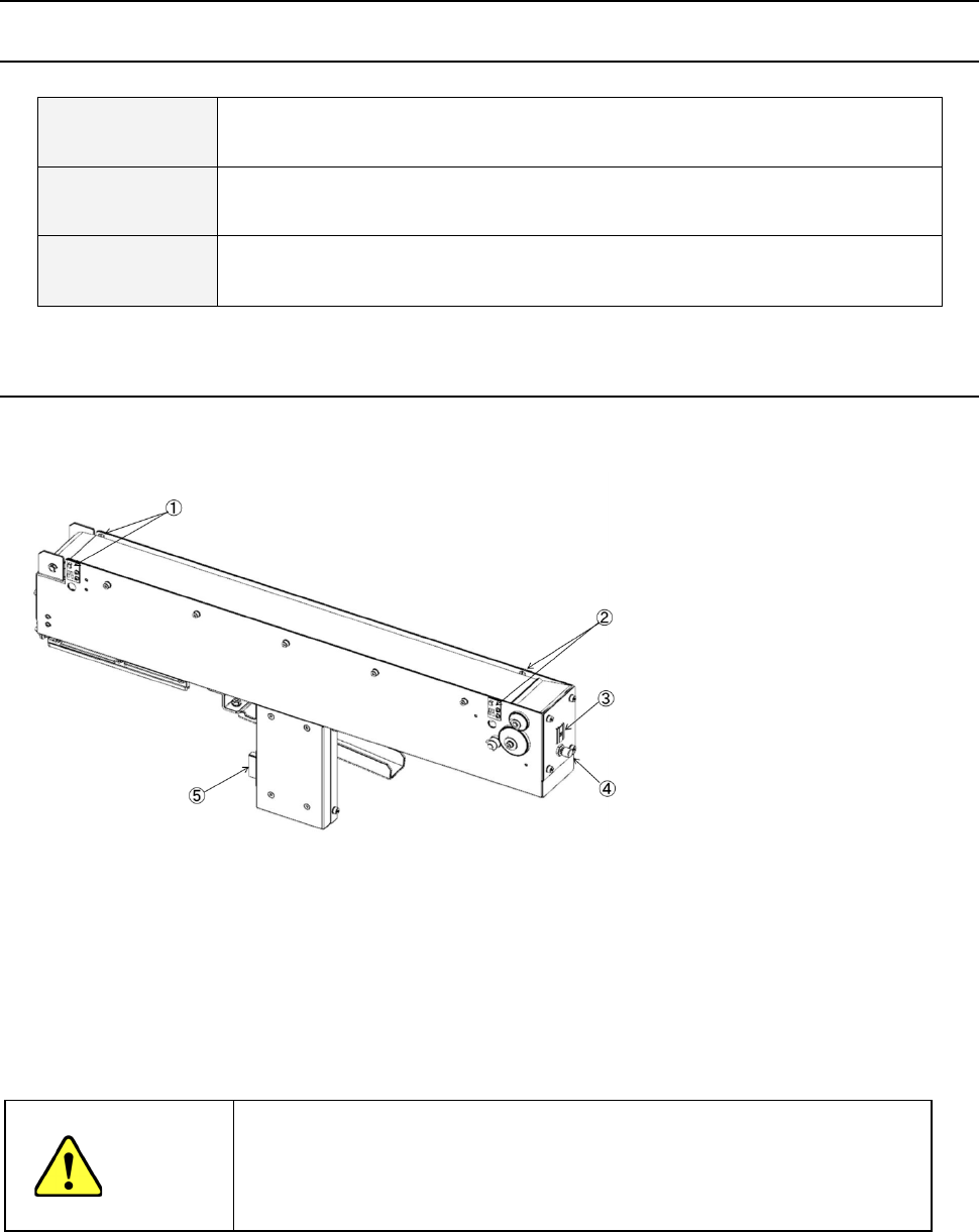
12.4.2 Configuration and parts identification of the IC collection belt
IC collection belt for electric bank
- This unit allows the machine to collect components which are not placed on a board for
some reason without damaging them after the components are recognized with the VCS.
• Components which are placed on the component sensor ① from the head are fed
sequentially at the pitch selected with the rotary switch ③.
• When the belt is full of components and the Stop sensor ② detects a component, the
main unit pauses and displays the message on the screen.
CAUTION
- To prevent your body from injury and to avoid damage to the machine, check to
see if the machine main unit stops completely before opening the safety cover to
remove a component from the IC collection belt.
- If you remove components from the IC collection belt still attached on the feeder
bank, always keep in close touch with other operators.
① Component sensor
② Stop sensor
③ IC size setting rotary switch
④ Reset switch
⑤ Power plug
Part 2 Detailed Description of Each Function Chapter 12 Handling the Optional Devices
12-28
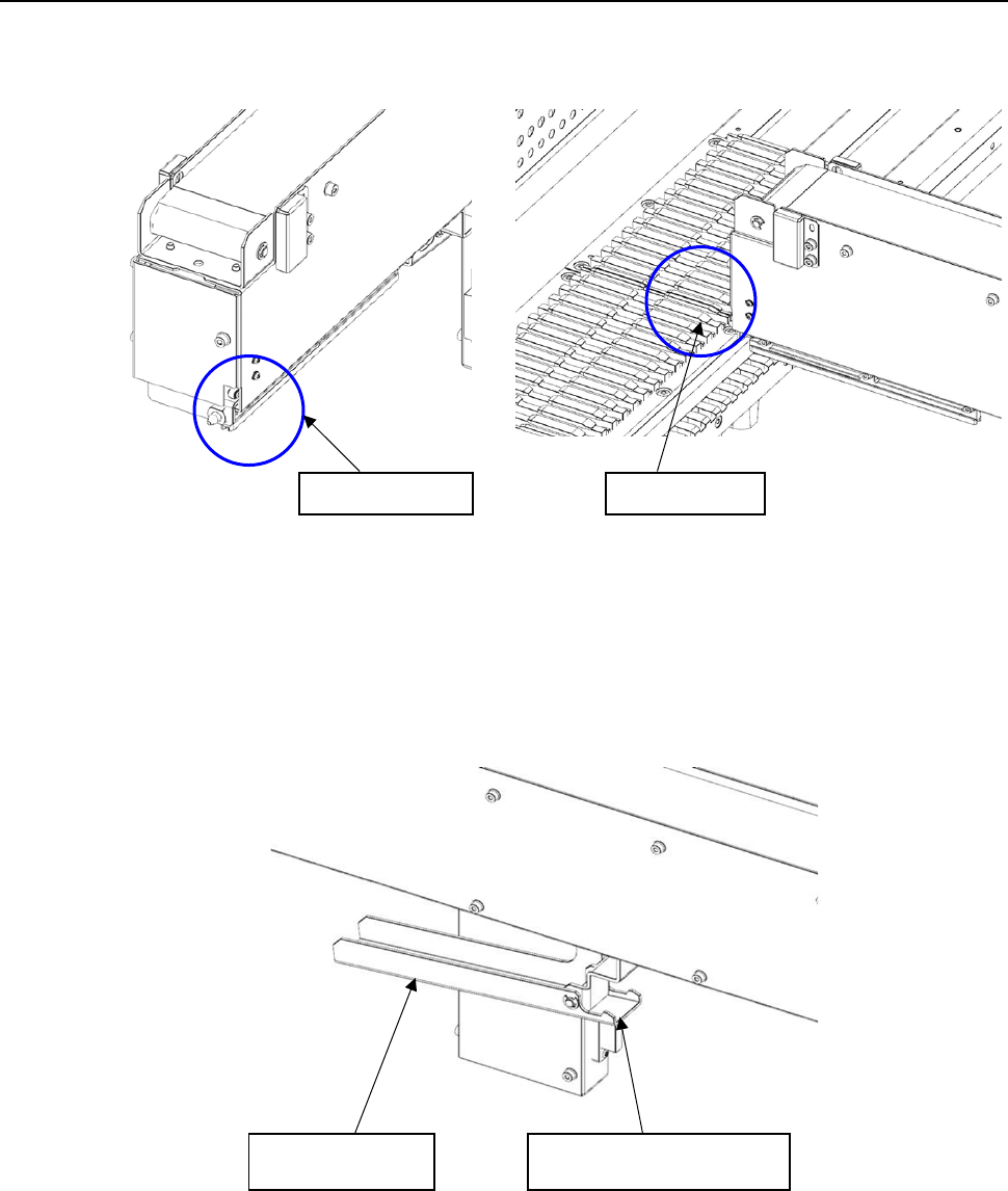
12.4.3 Attaching and detaching the IC collection belt
(1) Insert the slide rail tip in the guide rail groove if the bank.
(2) When inserting IC collection belt up to the middle, grasp the lever, and open the lock holder.
Slide rail tip
Guide rail
Lever
Lock holder