RS-1_instruction manual.pdf - 第201页
Part 1 B asic O peration Chapter 2 Pr oduction 2- 90 Pick position correction ( 1) Overview When you pres s the “T race” button displ ayed in the Operatio n area wh ile the “Retry l ist” is displayed o n the scree n, the…
Part 1 Basic Operation Chapter 2 Production
2-89
10) Error (Detail – Coplanarity)
No.
Displayed error message
1 A coplanarity judgemennt error.
2 A coplanarity centering position error.
3 A lead count error.
4 A colinearity judgemennt error.
5 A coplanarity unit error.
6 A illegal data or illegal operation.
7 A coplanarity adjust error.
8 A time-out or other error.
9 A hardware error of coplanarity controler.
10 A measurement software error.
11 A lasor diode is abnormal.
12 A cable connection error.
13 The motor revolution is abnormal.
14 A memory of sencer is abnormal.
15 A initialize error of coplanarity unit.
16 An axis error of coplanarity measurement.
17 The component type can not be measured.
18 The component size is too large.
19 The component size is out of range.
20 The component height is too high.
21 The meas. mode isn't corr. or the compo. cann't be measured.
22 The electrode can not be measured.
23 A coplanarity sensor is unused.
Part 1 Basic Operation Chapter 2 Production
2-90
Pick position correction
(1) Overview
When you press the “Trace” button displayed in the Operation area while the “Retry list” is
displayed on the screen, the “Pick pos. adjust conditions” screen appears.
You can track a component pick-up position under the conditions specified on this screen to
correct the component pick-up position.
Components whose pick-up position is corrected are automatically replenished.
What to correct varies depending on the displayed data on the “Retry list” you invoked:
♦ When the “Retry list (Supplier)” appears
The system corrects a component pick-up position of the displayed component supply unit.
♦ When the “Retry list (Not placed)” appears
The system corrects pick-up positions of component supply units assigned to all unplaced
components.
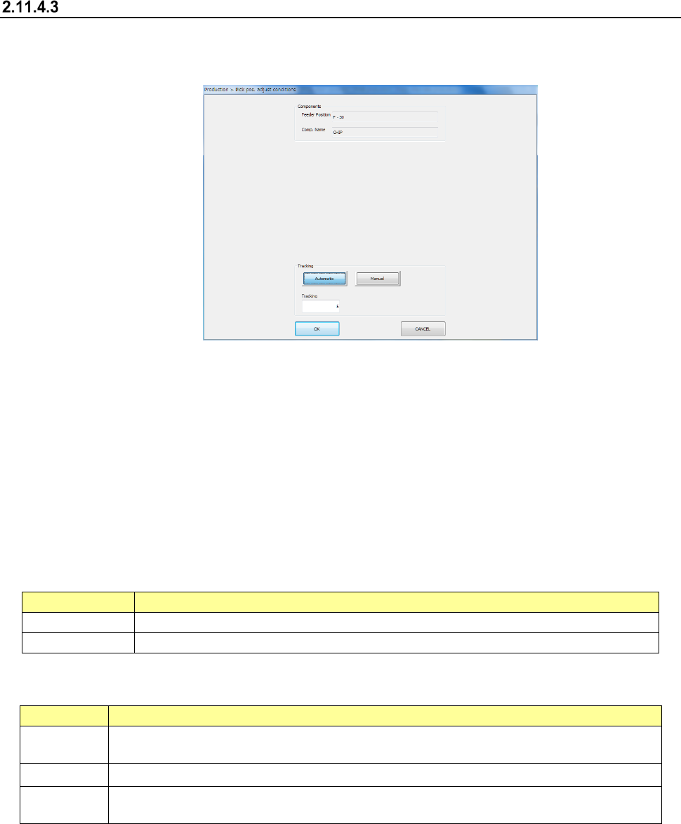
(2) Displaying the conditions for correcting the component pick-up position
1) Components
The pick-up position and name of a component to be corrected appear here.
Menu item
Description
Feeder Position
Displays the component pick-up position to be corrected.
Comp. Name
Displays the name of a component whose pick-up position is to be corrected.
2) Tracking
How to track a component pick-up position to be corrected appears here.
Menu item
Description
Automatic
The system stops at a component pick-up position for the certain time after correcting it, and
automatically moves to the next pick-up position.
Tracking
Specify the time period while the system has to stop when you select “Automatic” above.
Manual
The system pauses for the certain time after correcting the component pick-up position. The
system corrects the next pick-up point according to the operator’s input.
3) <OK> button and <CANCEL> button
When you press the <OK> button, the system tracks a component pick-up position, and
corrects it. Details of this operation are described in the next section.
When you press the <CANCEL> button, the system finishes correcting a component
pick-up position.
Part 1 Basic Operation Chapter 2 Production
2-91
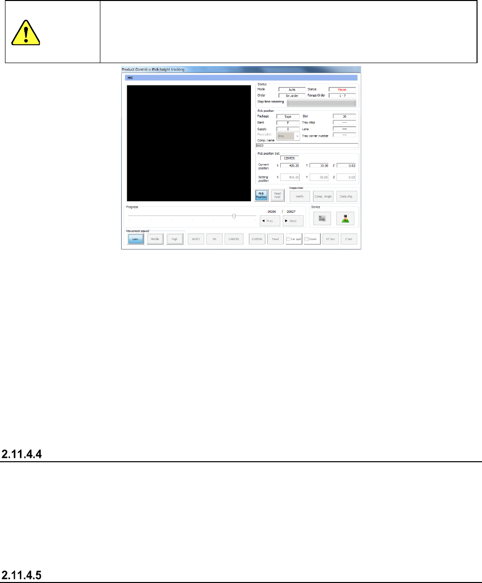
(3) Execution of tracking of a component pick-up position
When you press the <OK> button to start correcting a component pick-up position, the “Pick
position tracking” dialog box appears on the screen.
See Section 4.5.6.5 “Pick position/Pick height” of Chapter 4 “Creating a Production Program” or
Section 2.14.6 “Tracking a component pick-up position with a camera” for details of the
displayed data.
CAUTION
If the feeder bank is never recognized (for example, immediately after the devices of the
machine return to their home positions or the bank moves down then up), the feeder may be
recognized automatically before the machine moves to the pick-up position. Since the
head moves across the feeder bank while the feeder is being recognized, do not place your
hand or head in the machine, nor move your hand or face close to the machine.
1) When you select <Automatic> of the “Tracking” buttons
Before the system starts placing a component on a board, the camera moves to the first
component pick-up position, and displays the monitored image on the screen.
The camera stops at this position for the time specified in the “Tracking” field, and then
automatically moves to the next pick-up position.
To quit this automatic tracking operation for correcting a component pick-up position, press the
<STOP> switch of the operation panel. If you press the <STOP> button when the system
pauses, the camera stops at the current pick-up position. If you do when the camera is moving
to the next pick-up position, it stops at the next pick-up position.
2) When you select <Manual> of the “Tracking” buttons
After the system corrects the first pick-up position, it finishes tracking a pick-up position.
When you press the <START> button on Pick-up Position Correction mode, the system corrects
the next component pick-up position.
Teaching during tracking of a component pick-up position
If the tracked component pick-up position is found to be different from the actual pick-up position as
result of tracking described in the previous section, you can teach the component pick-up position
also.
When you press the displayed image on the touch panel: the upper, lower, left or right position,
you can change the current pick-up position. When you teach the coordinates and validate the
position, you can change the pick-up position set in the Pick data. Perform auto-teaching to
recognize the cavity for a component to be taught automatically.
Teaching the pick-up position
Select a feeder whose component pick-up position you want to teach when the “Retry list (Supplier)
is displayed on the screen, and then press the <Teaching> button displayed in the Operation area.
The system teaches the component pick-up position also.