RS-1_instruction manual.pdf - 第330页
Part 1 Basic Operat ion Chapter3 D aily maintenance 3- 38 3) R emov e the air tube and harnes s (power ground wi re) connec ted to the v acuum pu m p and then remove t he hexagon h ead shoulder bo lts (M6 x 13 mm) and he…
Part 1 Basic Operation Chapter3 Daily maintenance
3-37
3.7 How to replace the periodic replacement parts
* It is very dangerous to replace the cutter blade. To replace the cutter blade, ask our service
division or agent to replace it. For details, make inquiries at the information service.
The pressure may be lowered due to abrasion of the following parts:
<List of consumable parts>
Part number of the consumable parts kit: 40138045
Where to check
Quantity
of use
What to check
How to
check
Cup packing 2 Abnormal abrasion, hardening, and crack Visual check
Cylinder gasket 2 Deformation, hardening and crack Visual check
Air suction/release valve 2 Deformation, hardening and chip Visual check
O-ring S-647 2 Deformation, abrasion, hardening and crack Visual check
Head gasket 2 Deformation, hardening and crack Visual check
Check/
replacement
Replacement of stylus pen and long key holder
Preparation for replacing the vacuum pump
1) Check to see if the vacuum pump does not operate. (After the pump operates, the inside of the
pump gets hot. Therefore, leave the pump for approximately 30 minutes after it stops, and then
start replacing it only after making sure that it is cooled down.)
2) Remove the front lower right cover of the machine main unit.
Check/
replacement
Replacement of a cutter
unit
Tools to be used:
Hexagon wrench and
driver
When to replace
(guideline): One year
Check/
replacement
Replacement of a part of a
vacuum pump
Tools to be used:
Hexagon wrench
and screwdriver
When to replace
(guideline): One year
Cover (Screw × 4)
Part 1 Basic Operation Chapter3 Daily maintenance
3-38
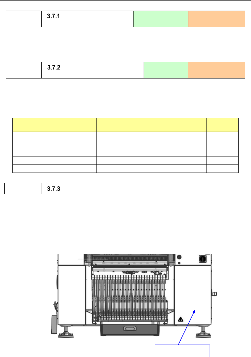
3) Remove the air tube and harness (power ground wire) connected to the vacuum pump and then
remove the hexagon head shoulder bolts (M6 x 13 mm) and hexagon nuts that fix the
VACUUM_PUMP_STAY.
4) Take out the vacuum pump from the main unit.
*
When taking it out, take care about the harness.
* When removing the vacuum pump, take care not to hold the connecting pipe.
* When taking out the vacuum pump, The rubber leg of a vacuum pump and VACUUM_PUMP_BR
may adhere.
Connecting pipe
Power ground wire
VACUUM_PUMP_ST
VACUUM_PUMP_BR
Air tube
Hexagon head
shoulder bolt x 2
Hexagon nut x 2
Part 1 Basic Operation Chapter3 Daily maintenance
3-39
Replacing the gasket
1) Remove four hexagon headed bolts (M6×95) (total eight bolts on the left and right sides) from
the pump head cover.
2) Remove the total of two black gaskets from the inside of the pump head cover, and then replace
them with new gaskets.
* Make sure that the gaskets are fit in the gasket groove of the pump head cover.
3) Tighten the hexagon headed bolts (M6×95) fixing the pump head cover and located in diagonal
lines at 5.0 N·m.
* To replace another consumable part with a new one, see the description of the procedure for
replacing the corresponding part without closing the cover.
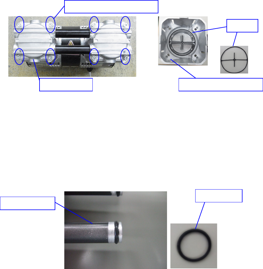
Replacing the O-ring P-10
1) Remove the pump head cover and the connecting pipes in the manner described in the
procedure for replacing the gasket above.
2) Attach the O-ring P-10 on the connecting pipe that connects two pump head covers.
3) While taking care not to damage the O-ring when inserting the connecting pipe, replace the
O-ring with a new one. (Replace two O-rings on both sides of each pipe.)
* Before replacing the O-ring, clean the O-ring groove of each connecting pipe and the connecting
pipe attachment hole of the pump head. To assemble the cover, follow the procedure for
replacing the gasket. To replace another consumable part with a new one, see the description
of the procedure for replacing the corresponding part without closing the cover.
Pump head cover
Inside of the pump head cover
Gaskets
Hexagon headed bolts (M6
×
95)
O-ring P-10
Connecting pipe