RS-1_instruction manual.pdf - 第345页
Part 1 B asic O peration Chapter 4 Cr eating a Produc tion Progra m 4- 10 4.3.3 .2 Dimension setup A production program represents a p osition of a com ponent or that of a mark on a board as coordinate s. The origin of t…
Part 1 Basic Operation Chapter 4 Creating a Production Program
4-9
3) Global bad mark
Specify whether to recognize a bad mark when the system recognizes a global bad mark.
4) Bad mark type
Specify a component placement operation to be performed when a bad mark is detected.
♦ No placement by mark:
Select this button so that the machine cannot place any component on a board when it
detects a bad mark.
♦ Placing by mark:
Select this button so that the machine can place a component on a board when it
detects a bad mark.
5) Specify Extended Bad Mark coordinates
Specify a position from which the bad mark coordinates are viewed, the origin of a circuit or
that of a board. If you select the “Extend” radio button when you select the “Used” radio
button in the “Multi circuit references” column, the system automatically specifies the
coordinates viewed from the origin of the reference circuit.
♦ Standard: When the bad mark is set at the same position as each circuit,
select this mark.
♦ Extended: This mark can be set at the coordinates having no same space as
the circuit pitch.
6) Bad mark teaching information
Select whether to use the bad mark teaching information of a production program.
7) Traceability (Production management system option)
◆ Not used: Select this item not to use the traceability.
◆ Used: Select this item to use the traceability.
8) Bad mark propagation (Production management system option)
◆ Not used: Select this item not to use the bad mark propagation.
◆ Used: Select this item to use the bad mark propagation.
9) Print offset feed forward (Production management system option)
◆ Not used: Select this item not to use the print offset feed forward.
◆ Used: Select this item to use the print offset feed forward.
10) Code specification
◆ Not used: Select this item not to use the code specification.
◆ Two-dimensional code (OCC): Select this item for production using the two-dimensional
code (OCC).
* When the two-dimensional code (OCC) is selected, the [Detail setting] button is enabled,
so that detail setting can be performed
* Regarding the detail setting, refer to “Instruction Manual for the production management
system.”
11) Circuit to Be Placed
You can select a circuit on which any component is not placed if “Matrix Circuit” or
“Non-matrix circuit” is selected as the “PWB configuration.”
Part 1 Basic Operation Chapter 4 Creating a Production Program
4-10
4.3.3.2 Dimension setup
A production program represents a position of a component or that of a mark on a board as
coordinates.
The origin of this “coordinates system on a board” is called as the “board reference position”.
・ The board reference position can be set at a desired position on or outside a board.
・ If you use CAD data to create Placement data, use the origin of the CAD data.
The relative position of the “board reference position” to the board positioning mechanism is to be
adjusted with the “board layout offset.”
On the “Dimension setup” screen, settings you have to make vary depending on selection of the
menu item “PWB configuration” (“Single PWB,” “Matrix circuit” or “Non-matrix circuit”).
Furthermore, the items displayed on the screen also vary depending on the positioning method,
usage setting of bad mark, and that of BOC.
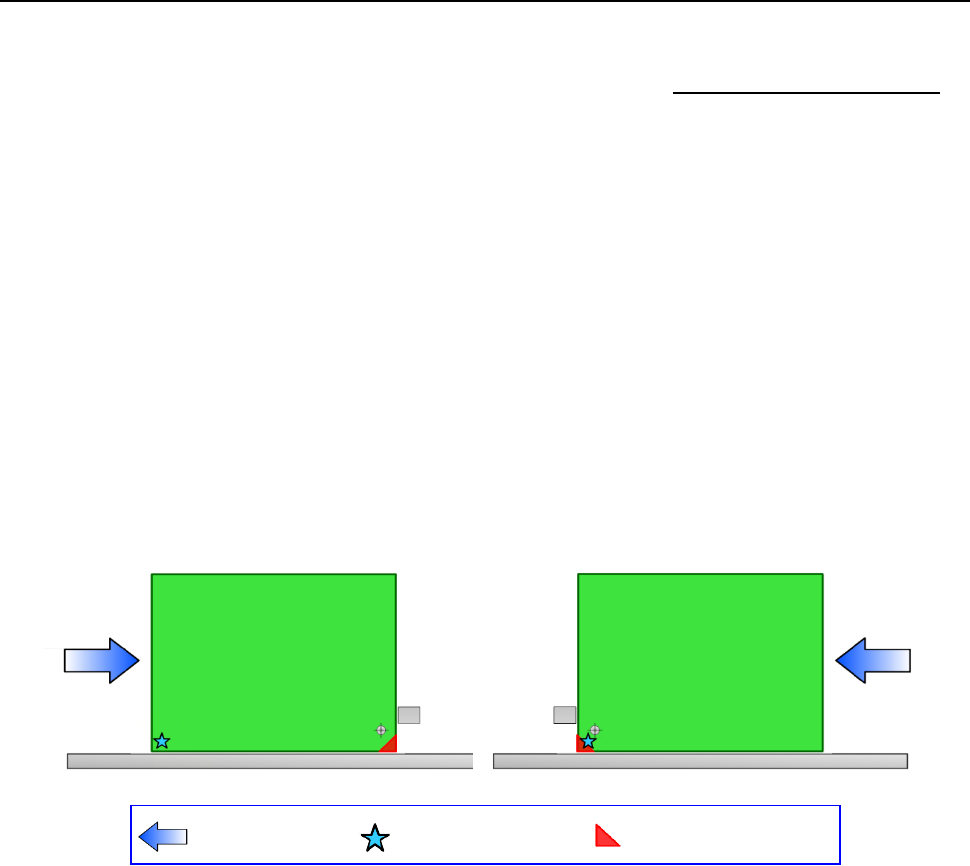
(1) Reference
The layout end point of a board is defined according to the board transport direction as shown in
the figure below.
1) Transport direction: left to right
2) Transport direction: right to left
Transport direction
Board reference position
(desired
position)
Board layout end point
Part 1 Basic Operation Chapter 4 Creating a Production Program
4-11
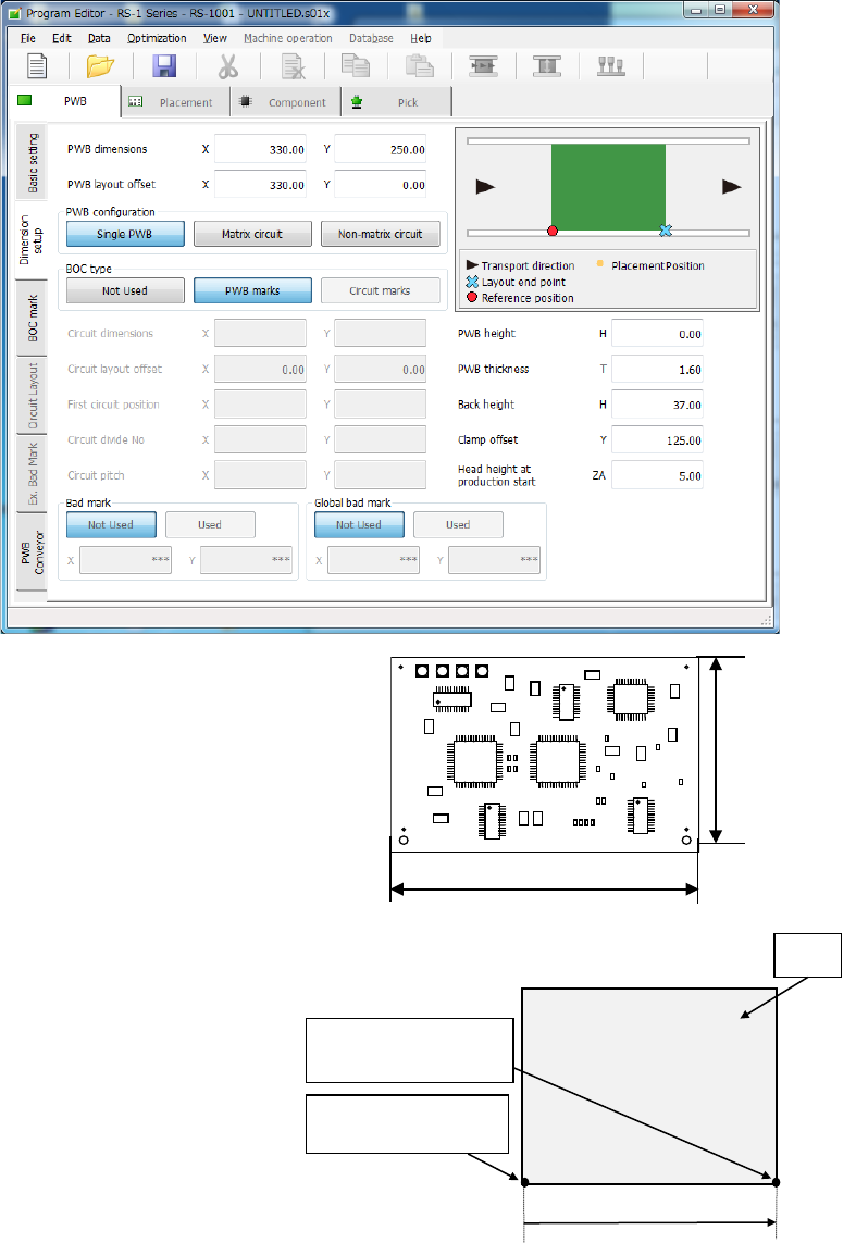
(2) Single circuit PWB
Single-circuit PWB means a PWB on which only one circuit exists.
1) PWB dimensions
Enter the dimensions of a PWB here.
If the machine is supplied with a
dummy PWB, enter the dimensions
of this PWB also.
The same direction as the transport
direction is X and the direction
perpendicular to the transport direction is Y.
2) PWB layout offset
Enter the length from the PWB
position reference to the end point
of the PWB layout.
Enter the distance from the PWB
origin defined by the CDA or other
tool to the reference position (PWB
layout endpoint) if the specified
origin (the CAD origin or an origin
that is unique to a user) must be
used as the PWB origin, for
example, in a case in which CAD
data is used.
When transport is performed by front reference and the PWB flow direction is left to right,
the PWB layout end point is “reference position.” When the PWB reference position is at
the left lower corner of the PWB, enter the (Xb, 0) value in each of the X and Y coordinates
of the PWB layout offset. The Xb is a positive value.
PWB reference
position
PWB
Yb = 0
Xb
PWB layout endpoint
(Reference position)
Dimension X
Dimension Y