RS-1_instruction manual.pdf - 第242页
Part 1 B asic O peration Chapter 2 Pr oduction 2- 131 The “Product ion lane infor m ation” t ab allows you to disp lay/hi de the product ion lane inf ormation on the upper sect i on of the “Production st atus (Vision)/( …
Part 1 Basic Operation Chapter 2 Production
2-130
2.13 Tool
Operation option
When you select the [Tool] command from the “Product” menu, and then the [Operation option]
command, the “Operation option” screen appears.
See Chapter 7 “Operation Option” for details.
Setting of the displayed items
When you select the [Tool] command from the “Product” menu, and then the [View Log File]
command, the error log display screen appears.
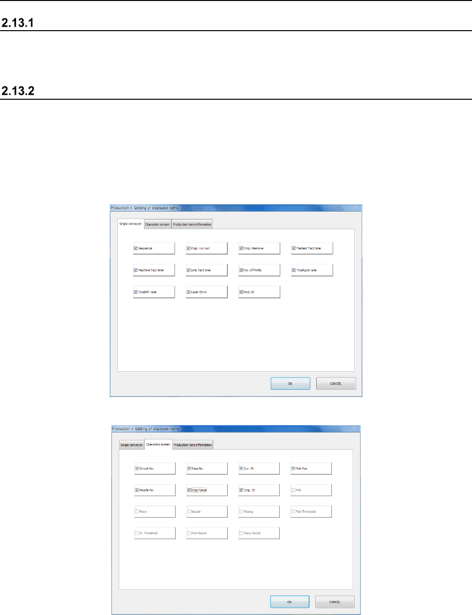
This screen allows you to display or hide an item to be displayed during PWB production.
The items displayed on the “Production condition” screen when the machine uses the single-lane
conveyor to produce PWBs are different from those when it uses the dual-lane conveyor to produce
PWBs.
The “Single conveyor” tab allows you to display or hide the items on the “Production condition”
screen when the machine uses the single-lane conveyor to produce PWBs.
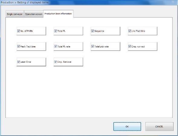
The “Operation screen” tab allows you to display/hide menu items on the “Production status
(Operation condition)” screen.
Part 1 Basic Operation Chapter 2 Production
2-131
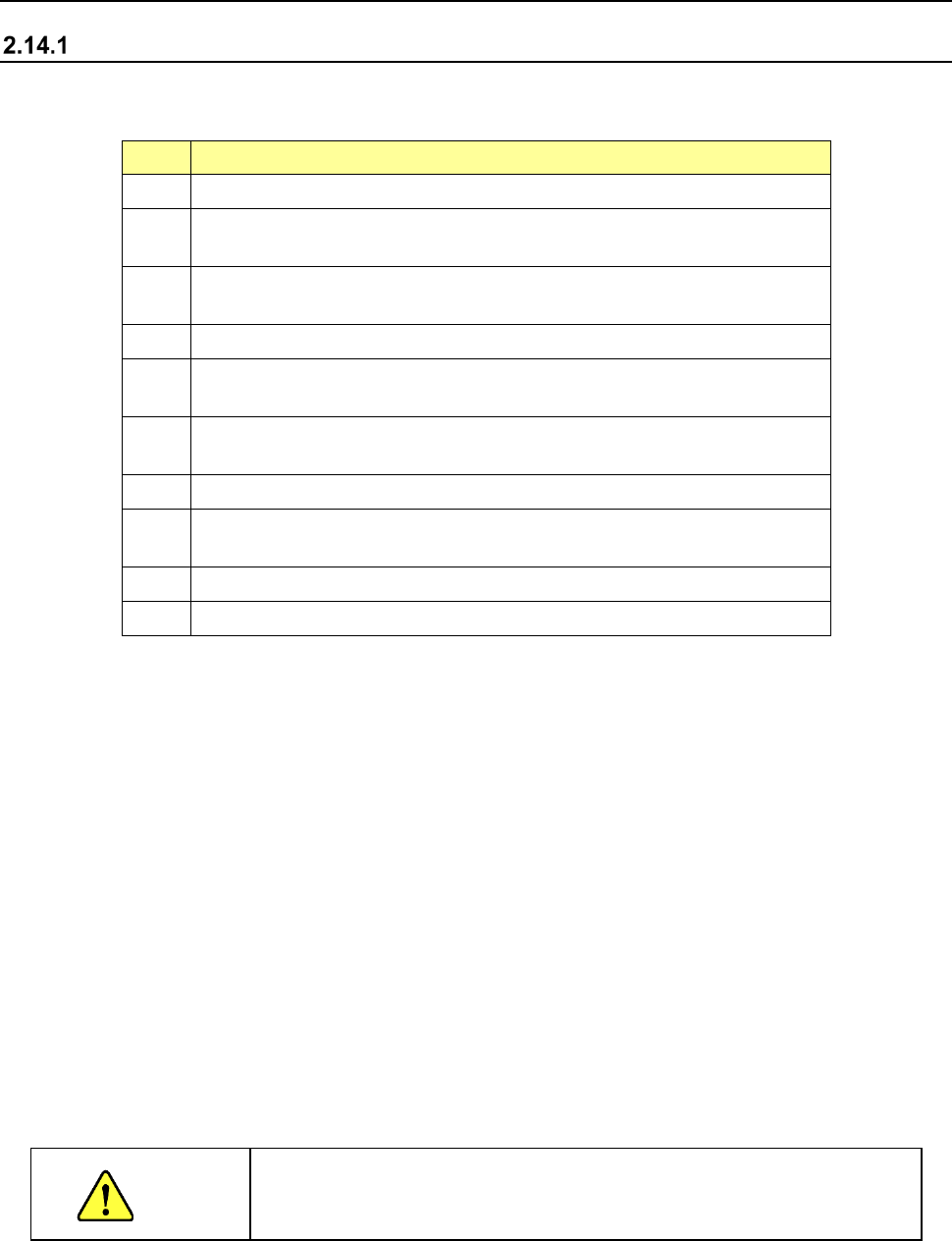
The “Production lane information” tab allows you to display/hide the production lane information on
the upper section of the “Production status (Vision)/(Operation condition)/(Number of produced
PWBs)” screen.
Part 1 Basic Operation Chapter 2 Production
2-132
2.14 Process of PWB Production
Conditions necessary to operate the ZA-axis at a 3mm-height
The following shows the conditions necessary to operate the ZA-axis at a 3mm-height. To operate
the ZA-axis at a 3mm-height, all of the following conditions need to be satisfied.
No. Conditions
1 "Head height at production start" of the Machine Setup is 1 mm or less.
2 The maximum value of "component height + pickup depth" of a component to
be placed by this machine is 1 mm or less.
3 The maximum diagonal length of a component to be placed by this machine is
less than 86 mm.
4 The maximum pickup height is 1 mm or less.
5 The maximum component height + PWB height (only when the PWB height is
positive) of a component to be placed by this machine is 1 mm or less.
6 The component height - placing stroke (only when the placing stroke is
negative) is 1 mm or less.
7 The height of the placement PWB surface is not measured.
8 The height of the head at the production start of the production program is 1 mm
or less.
9 No RF/EF bank, MTC, and MTS are mounted.
10 Only the RF type feeder is mounted on the RF bank.
* Whether the ZA-axis can operate at a 3mm-height is judged on the front and rear.
When the front supply is possible at a 3mm-height and the rear supply is impossible at a
3mm-height, the ZA-axis operates at a 3mm-height only during front supply.
◆ The operation at the ZA-axis height may vary depending on the number of transport buffers.
1) When the option “ZA-axis operation with the substrate size for 3 buffers” is disabled in
3-buffer mode, the height of the ZA-axis is adjusted to the highest one of all component
placement positions.
2) When the option “ZA-axis operation with the substrate size for 3 buffers” is enabled in
3-buffer mode*, the ZA-axis is adjusted to the highest one of the positions at which
components have been already placed.
3) In 1-buffer mode, the ZA-axis height is adjusted to the highest one of the positions at which
components have been already placed.
* Since the ZA-axis operates differently depending on the board size, see Section 12.6.4
“ZA-axis operation with the substrate size for 3 buffers” for details.
CAUTION
If any value shown above is set incorrectly, the head may interfere with other unit.
Be sure to enter the correct set values.