RS-1_instruction manual.pdf - 第451页
Part 1 B asic O peration Chapter 4 Cr eating a Produc tion Progra m 4- 116 The menu item s di spl ayed on t he “Control 2” tab and t hose on the “Contr ol 3” tab are sho wn in the table be low . Menu items Description “S…
Part 1 Basic Operation Chapter 4 Creating a Production Program
4-115
3) For the side light
The light control data (side light) screen allows you to set the input value of the side light.
The light control data (side light) screen is shown below.
When you select “Side lights” as the “Light type” and “Red” as the “Light style,” the “Blue
Side Light” check boxes are disabled. In the same manner, when you select “Blue” as the
“Light style,” the “Red Side Light” check boxes are disabled.
When you select the <OK> button, the settings of the light control data are enabled.
When you select the <Cancel> button, the settings of the light control data are disabled.
Part 1 Basic Operation Chapter 4 Creating a Production Program
4-116
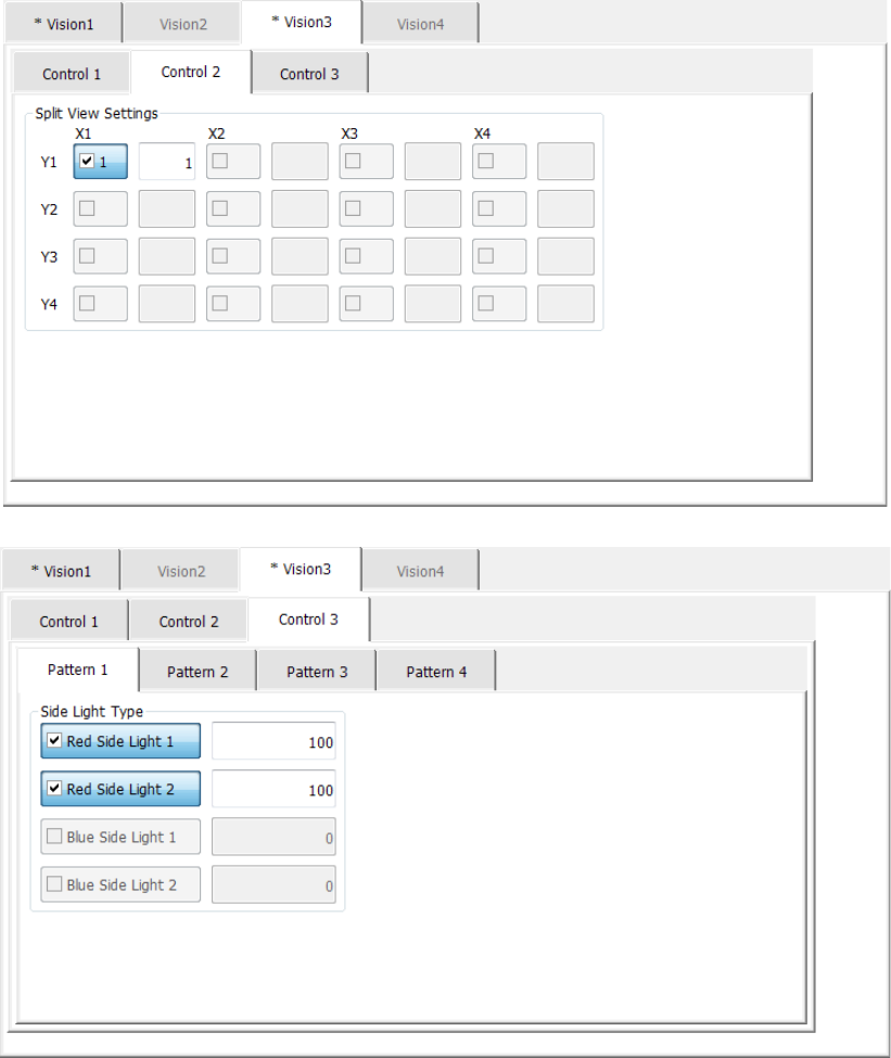
The menu items displayed on the “Control 2” tab and those on the “Control 3” tab are shown
in the table below.
Menu items Description
“Split View Settings” check boxes
Select the corresponding check box for dividing an image of a
component in the desired way.
“Split View Settings” light patterns Enter the light pattern number.
Light pattern check box
Select a check box when you use the light enabled according the
settings of the “Light type” and “Light style.”
- For the bottom light
You can select the check boxes: “Same Axis Light,” “Bottom Light,”
“Red Side Light 1” and “Red Side Light 2.”
- For the back light
You can select the check boxes: “Front/Rear” and “Left/Right” on
the “Bottom” and “Front/Rear” and “Left/Right” on the “Top.”
- For the side light
You can select the check boxes: “Red Side Light 1,” Red Side
Light 2,” “Blue Side Light 1” and “Blue Side Light 2.”
Light pattern control level
Enter the control level of the light enabled according to the settings of the
“Light type” and the “Light style.”
The input range is from 10 to 200 %.
Part 1 Basic Operation Chapter 4 Creating a Production Program
4-117
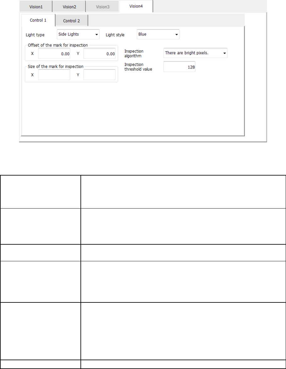
(14) Setting for determining the side of a component, the top or the bottom/checking the direction
of a component
When you select the “Vision 4” tab, the following screen appears.
The “Control 1” tab allows you to make settings of recognition, while the “Control 2” tab allows you
to make the detailed settings of the lights.
Make the settings of the lights only to inspect the direction of a BGA or FBGA component.
Light type
(Only for a BGA or FBGA
component)
Select the light type:
- Bottom Lights
- Back Lights
- Side Lights
Light style
(Only for a BGA or FBGA
component)
Select the detailed light types:
- Standard
- CBGA
- LGA
- Blue
- Red
- Fine
Offset of the mark for
inspection
Set the offset from the center of the component to that of the recognized
part in the range of -50 to 50.
Size of the mark for
inspection
Specify the window size for image recognition in the range of 0.01 to 50.
When the component type is “Chip” (square chip), the default size is the
shorter side*, 0.7 mm.
When the component type is “BGA” or “FBGA,” this field is blank by
default.
Inspection algorithm
Select the algorism for image recognition.
The mean value is bright.
The mean value is dark.
There are bright pixels.
There are dark pixels.
The standard deviation is large.
The standard deviation is small.
Inspection threshold value
Specify a threshold value for image recognition in the range of 0 to 255.
The settings that you are supposed to make on the “Control 2” tab are the same as those of the
“Control 3” tab of the “Vision 3” tab. (Note that only the “Pattern 1” tab is displayed on this tab.)