RS-1_instruction manual.pdf - 第549页
Part 1 B asic O peration Chapter 4 Cr eating a Produc tion Progra m 4- 214 (2) E xecut ing the BO C alignm ent operat i on Immediate ly after the cam era starts trackin g a component placem ent positi on, the system exec…
Part 1 Basic Operation Chapter 4 Creating a Production Program
4-213
4.5.6.4 Place
This command uses a camera to track a component placement position. You can check the
component placement position displayed on the monitor, so you can teach and edit it if the position
is not appropriate.
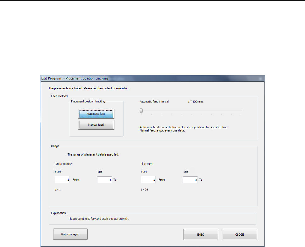
(1) Setting the tacking conditions
When you select the [Machine operation] command from the Program Editor menu, and then the
[Place] command, the following screen appears.
1) Feed method
a) Automatic feed
The camera shoots a component placement position one by one at regular intervals. The
camera stops for the time of period specified with the “Automatic feed interval” slider bar
displayed below, then moves to the next position.
• Automatic feed interval:
Use this slider bar to adjust the stop time. You can set the interval from 0.01 second (10
ms) to 5 seconds.
b) Manual feed
The system stops at each component placement position.
The operation is stopped until the user performs an operation.
2) Range
Select a circuit No. and placement point for executing tracking.
Enter the range of Placement data used for tracking: from the start point to the end point.
By default all placement positions are to be tracked.
After you specify all of the setting items, press the <Start> switch or click the <Execute>
button.
When you click the <CANCEL> button, the system returns to the previous screen.
Part 1 Basic Operation Chapter 4 Creating a Production Program
4-214
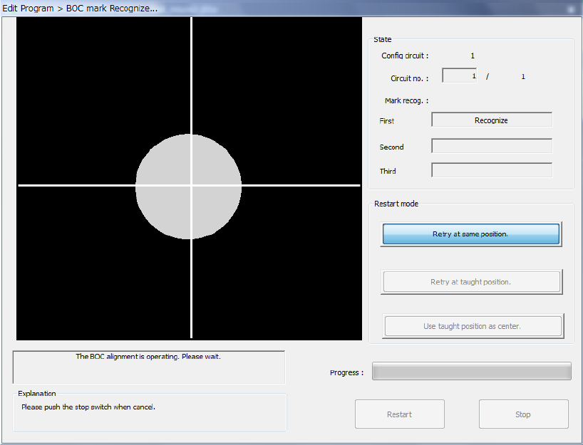
(2) Executing the BOC alignment operation
Immediately after the camera starts tracking a component placement position, the system
executes BOC alignment operation to improve the precision of the component placement position
if a production program on which a BOC mark is set is used. (BOC marks of all circuits are to be
recognized.)
Part 1 Basic Operation Chapter 4 Creating a Production Program
4-215
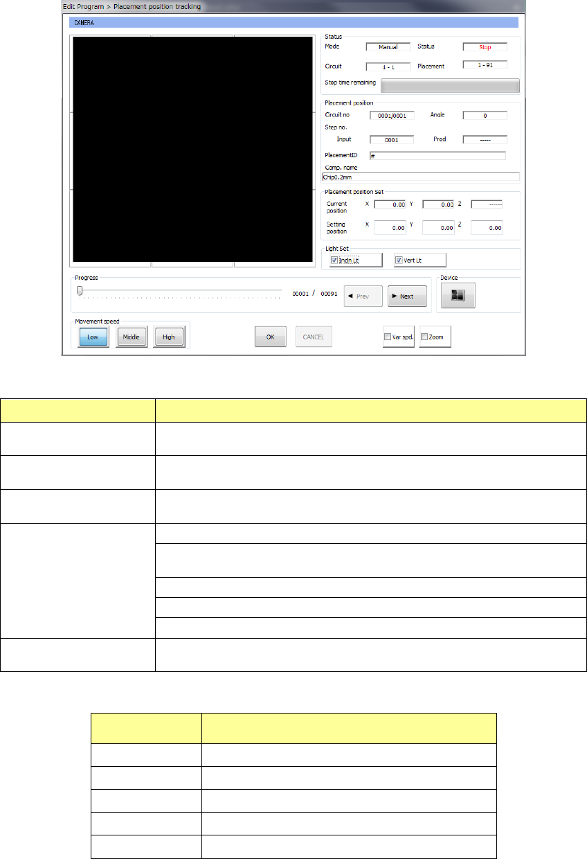
(3) While the camera is tracking a component placement position
After a component placement position is tracked, or while each component placement coordinate
is being tracked, the following dialog box appears.
1) Status
Menu item
Overview
Mode
The feeding method specified with the menu item “Feed method,”
“Auto” or “Manual,” is displayed here.
Circuit
The range of circuits to which placement tracking is to be
conducted is displayed here.
Placement
The range of component placement positions to which placement
tracking is to be conducted is displayed here.
Status
“Moving” indicates that the axis is moving.
“Pause” indicates that the axis stops temporarily in Automatic Feed
mode.
“Stop” indicates that the axis stops manually or intentionally.
“Axis esc” indicates that the axis is moving to the safety position.
“Mark recog” indicates that the system is recognizing an IC mark.
Stop time remaining
The progress bar shows the remaining stop time in Automatic Feed
mode.
2) Placement position
Menu item Overview
Circuit no Circuit being measured/Total number of circuits
Angle Component placement angle being measured
Step no. Placement data number being measured
Placement ID Placement ID being measured
Comp. name Name of a component being measured