RS-1_instruction manual.pdf - 第948页
Part 2 D etaile d Descript ion of E ach Functi on Chapter 12 Handling th e Optional Device s 12 - 64 (3) Setting the sol der shap e Sp ecif y two upper left and lower right po ints of the wind ow so that i t can com e in…
Part 2 Detailed Description of Each Function Chapter 12 Handling the Optional Devices
12-63
You can continue teaching, and use the automatic adjustment function on the “Set Solder
Recognition Parameter” screen in order to set the parameters automatically.
After adjustment, select the <OK> button. The system updates the adjustment value and
goes to the next process.
When you select the <APPLY> button, the adjustment value is updated. When you select
the <CANCEL> button, the system stops teaching.
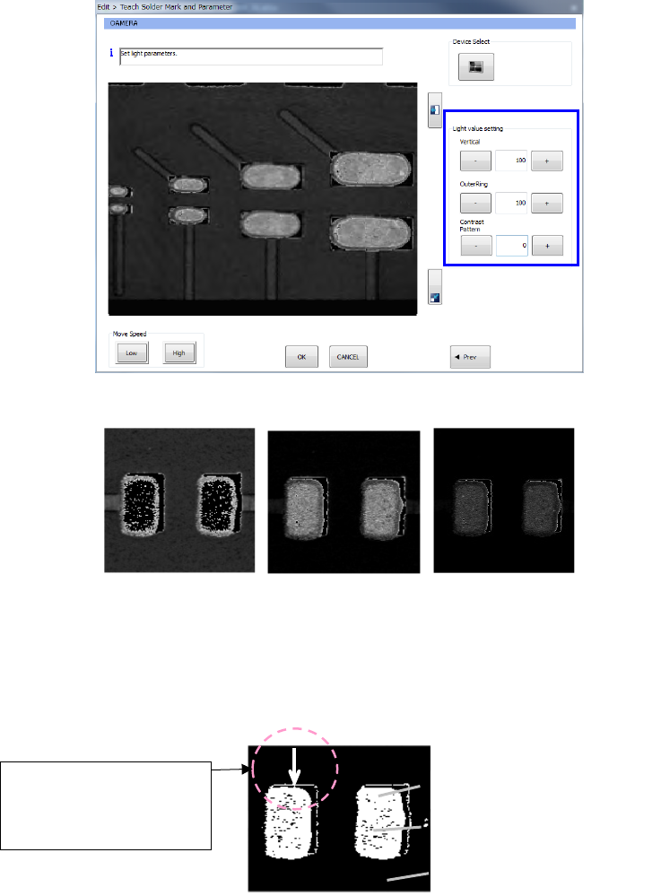
- Example of recognition images (Left: Too bright, Center: Good, Right: Too dark)
(2) Setting a binary threshold value
Use the upper and/or lower arrow key to adjust a binary threshold value so that only solder
displayed on the monitor can look bright.
Like the outline of the electrode pad displayed in the Figure 12.12.8.6, any gloss of about one
pixel other than solder will not affect recognition of solder.
You can continue teaching, and use the automatic adjustment function on the “Set Solder
Recognition Parameter” screen to set a parameter automatically also.
If you cannot adjust the threshold value easily, use the PERVIOUS key to return to the light
adjustment screen and readjust the light.
Solder
Electrode pad
Resist section of a board
If the thickness of the
outline is about one pixel,
it will not affect
recognition of solder.
Part 2 Detailed Description of Each Function Chapter 12 Handling the Optional Devices
12-64
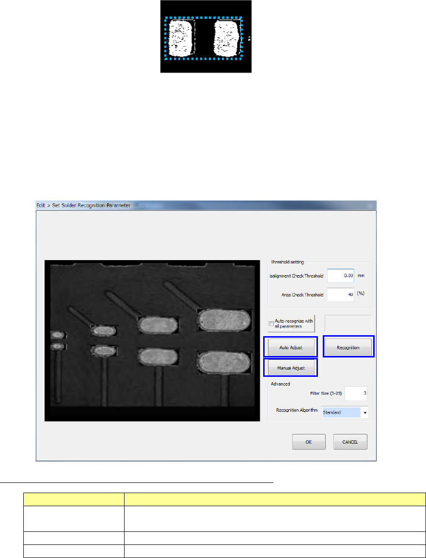
(3) Setting the solder shape
Specify two upper left and lower right points of the window so that it can come in contact with
a pair of screen-printed solders by operating the screen, and select the [OK] key.
(4) Setting a misalignment check threshold value
Enter a misalignment check threshold value to be detected by the solder position
misalignment check and the area ratio threshold value to be detected by the condition check.
The detection area is to be “the solder dimensions to be obtained during teaching” + “the
misalignment check threshold value.” When you select the <OK> button, the system
updates the threshold values and proceeds to the next process.
* The system sets the detection area based on the “Misalignment Check Threshold” value.
* When you enter “0” into the “Area Check Threshold” field, the system will not check the
area ratio.
Description of the command buttons displayed on the screen
Button name
Description
Auto Adjust This button automatically adjusts the lights, the threshold values and
the contrast pattern.
Recognized Result
This button recognizes a solder mark.
Manual adjustment
Moves to the manual adjustment screen.
<Operation with a keyboard>
1. Use the [Tab] key to move the focus into the edit box.
2. Enter the desired value into the edit box.
3. Use the [Tab] key to move the focus into the corresponding command button, and then
press the Enter key.
①
③
②
Part 2 Detailed Description of Each Function Chapter 12 Handling the Optional Devices
12-65
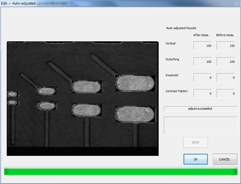
① (Parameter) Auto Adjust
When you select the <Auto Adjust> button on the “Set Solder Recognition Parameter” screen,
the system repeatedly changes each parameter to recognize a solder mark, and
automatically adjusts the parameters to the optimal ones. After the system automatically
finishes adjusting the parameters, the following “Auto-adjusted Results” screen appears.
If the system cannot recognize solder marks stably, it displays a warning.
When you press the F12 key on this screen, you can record two or more images displayed
during automatic adjustments. These images are stored in the same manner as the
recognized images displayed on the VCS monitor. However, this process requires much
time. To cancel this process, press the F12 key again or the Esc key. The dialog box
appears on the screen, and it allows you to cancel the image storage process or continue this
process.
② Recognized Result
When you press the <Recognized Result> button on the “Set Solder Recognition Parameter”
screen, the system recognizes solder marks according to the set parameters. When the
system succeeds in recognition, the cross mark appears at the center of the solder displayed
on the VCS monitor. If the system fails to recognize solder, the corresponding error code is
displayed on the VCS monitor. If the system cannot recognize solder stably, select the
<CANCEL> button on the “Set Solder Recognition Parameter” screen, and adjust the lights
again.