RS-1_instruction manual.pdf - 第417页
Part 1 B asic O peration Chapter 4 Cr eating a Produc tion Progra m 4- 82 Settings of some menu ite ms displayed on the “ Inspect ion” tabs may be r estri cted depending on the settings of ot her menu items such a s a “C…
Part 1 Basic Operation Chapter 4 Creating a Production Program
4-81
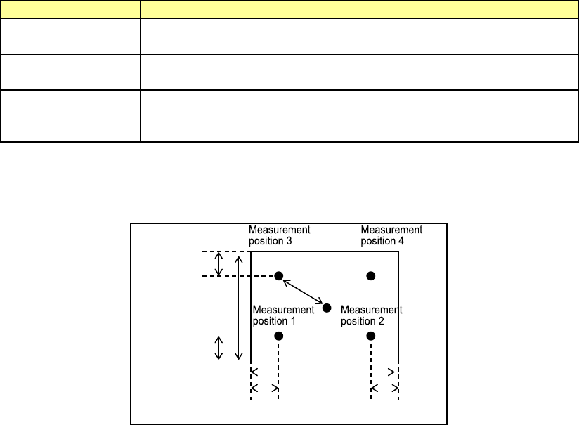
2) Height check after placing
This function checks to see if a placed component equipped with a boss does not incline by
measuring the height of each of four corners of the component with the HMS after the
component is placed on a board.
When the result is between a negative value set as the “Threshold” and a positive value set as
the “Threshold,” the function decides that the component is placed on the board normally.
If the result exceeds this range, the production stops temporarily.
Setting item
Description
Check
Specify whether to check the component height.
No. of Samples
Specify how many positions are to be checked between 2 and 4.
Threshold
Specify a value for deciding that a component is placed on a
board normally.
Offset X, Y
Specify where to check by offset values viewed from a positon at
which a component is placed. Specify measurement (check)
positions from the top, Position 1, 2, 3 and 4.
The figure below shows the relation between the offset value of each measurement position
and a positon to be checked.
Offset value
30 % of the
length
30 % of the width
30 % of the
length
30 % of the width
Part 1 Basic Operation Chapter 4 Creating a Production Program
4-82
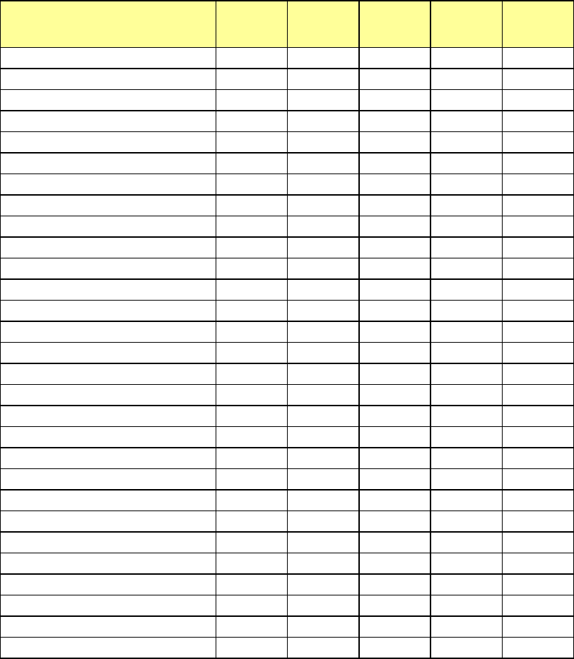
Settings of some menu items displayed on the “Inspection” tabs may be restricted depending on
the settings of other menu items such as a “Component Type.”
Component type Tombstone
Component
verification
Dimension
check
Component
direction
Pick
position
offset
Square chip
○ ○*1*2 ○ × ○
Square chip (LED)
○ ○*1*2 ○ × ○
MELF
○ ○*1 ○ × ○
Aluminum electrolytic capacitor
○ ○*1 ○ × ○
SOT
○ × ○ × ○
Trimmer
○ × ○ × ○
Network resistor
○ × ○ × ○
SOP ○ × ○ × ○
HSOP ○ × ○ × ○
SOJ ○ × ○ × ○
QFP ○ × ○ × ○
GaAsFET ○ × ○ × ○
PLCC (QFJ) ○ × ○ × ○
PQFP (BQFP) ○ × ○ × ○
TSOP ○ × ○ × ○
TSOP2 ○ × ○ × ○
BGA ○ × ○ × ○
FBGA ○ × ○ × ○
QFN ○ × ○ × ○
Outline recognition component
○ × ○ × ○
General-purpose vision
○ × ○ ○*3 ○
Unidirectional lead connector
○ × ○ × ○
Bidirectional lead connector
○ × ○ × ○
Z-lead connector
○ × ○ × ○
Extended lead connector
○ × ○ × ○
J-lead socket
○ × ○ × ○
Gull-wing socket
○ × ○ × ○
Socket with bumper
○ × ○ × ○
Other components
○ × ○ × ○
*1: Only when the longer side of the component outline size is 10.00 mm or less and the
"packaging style" is "tape", data can be entered.
*2: When the length of the shorter side is less than 0.45 mm, data cannot be entered.
*3: You cannot specify this menu item unless the outer dimension of a component is from
1.00×1.00 mm to 50.00×100.00 mm.
Part 1 Basic Operation Chapter 4 Creating a Production Program
4-83
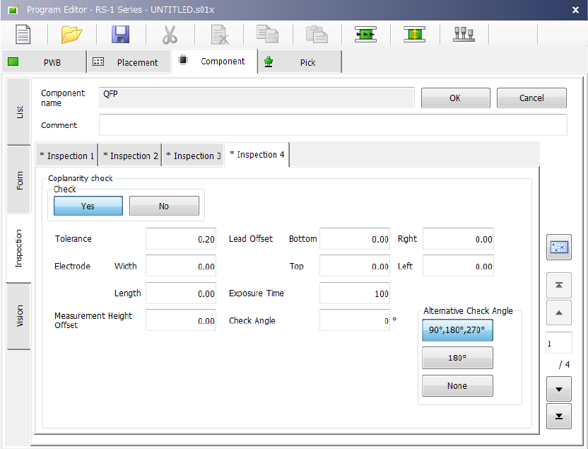
(10) Inspection 4
Set the “Coplanarity check” data on this tab.